Star Trek Ship Tutorial 3
page 4
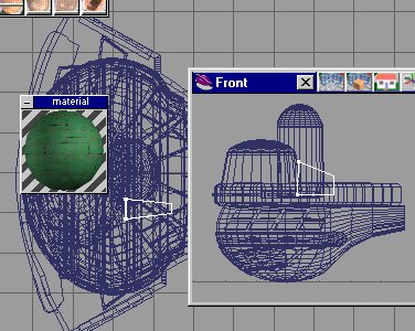
The Command Section
 Ref picture on the right.
Use the poly spline line tool and trace the shape using the top view.
Select the face with the face edit tool and sweep upward. see pic to the right.
I then like to bevel the top and bottem edges.
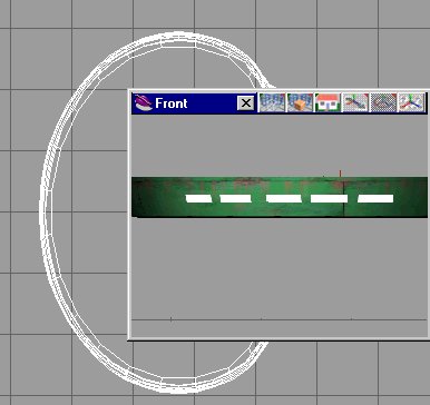
Now paint with green panels 4 X 4 .
Ref picture on the right.
Use the poly spline line tool and trace the shape using the top view.
Select the face with the face edit tool and sweep upward. see pic to the right.
I then like to bevel the top and bottem edges.
Now paint with green panels 4 X 4 .
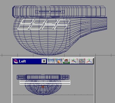
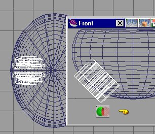
Since you are so good using the spline line tool , lets use it again .
Trace out som detail markings(hull lines) for the top.See picture below.

 Look at the picture on the right .
We will mow copy the new shape and subtract it from itself, using the object subtract tool (see hand)
Look at the picture on the right .
We will mow copy the new shape and subtract it from itself, using the object subtract tool (see hand)

picture on the left shows me beveling the top face.
 As you can see(from the picture on the right).
We need to make several of these hollow shapes detail thingys.
As you can see(from the picture on the right).
We need to make several of these hollow shapes detail thingys.
We make several of these and glue them all together as seen in the picture to the right.

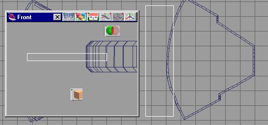
Next , select a box, stretch it and place it as show in the picture on the left. Paint it with green panels. Select the box coy it shrink it and paint it white . Copy 3 more times and glue together.
These new boxes will be our cut out window tool .
Position them as show in the picture on the left.


Your model should look like this (see pic on the right).
Select the ball shape . Se picture on the left.

Now select the box shape and position it as shown in the picture on the right. We will subtract the box from the ball with the object subtract tool .

Next cut the back off of the ball shape just like we did with the top. After the cuts , stretch the modified ball shape to match the schematic. Your shape should look like the picture on the left.

Selct the rear face of the ball with the face edit tool. We are going to sweep this edge out.

Since this is a tutorial , lets use a new tool . The shape deformation tool . I love this tool .The icon looks like an egg. Left click it and the drop down menu appears . There are 3 controls in the middle row. Sellect the object then select the control . the object turns green and orange. Move the arrow to the right and more segments appear in green.
These are modifier sections . With the pointer select a green line .
Now select one of the controls on the modifier menu row one.
Lets choose the top one . This moves or stretches the section in the direction you move the arrow.
If we choose the bottem control it will shrink of enlarge the section which you have selected .
Play with this tool , it can do a lot. Use this tool till your ball looks like the picture above left.
You will recall the little cutout line boxes we made for the top . We will do the same for the side.
Make a box , copy it , stretch it , subtract it from the other.
You know the drill by now. Then copy and glue together.
I did this 8 times . See picture to the right.
Stretch this shape out as shown. Now I save a lot .
Save the ball shape . Subtract the hollow boxes from the ball shape.
Then stretch it out just a bit. Now load your ball shape again. Glue together the shapes.
What you want more detail?
Top view , trace out some more shapes , see picture on the right . We shall leave them solid this time(just for grins).
Glue them all together . Select them with the face edit tool and sweep up. Then rotate then 90 degrees, then rotate to allign with the ball hull shape.

See picture to the right. We shall do the object subtract operation again.

Reload your ball shape .Take the cut out and strech it just a bit, paint dark green and glue to the ball.
Save again.
Let put in a windows section . Select a box shape .Stretch it and position it like the one in the picture to the left.

Copy the boy and rotate .
Then copy the box again till you have 4 windows, glue them together.
Copy them and make an inverse using the inverse copy tool.
See picture on the right.We are going to cut again, select the object subtract tool .
Select the boxes and paint htem white.
Cut out the boxes
See picture to the left.Reload the command section . Glue this part to it.
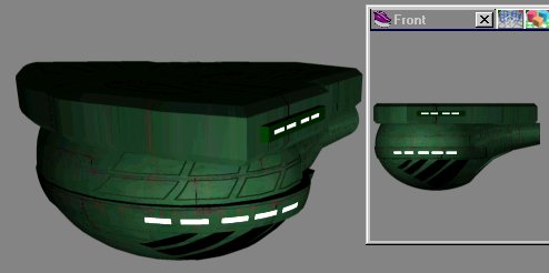
Your model should look like this: See picture on the right.
That forward section looks a little plain.
Let's add a sensor array. Select a box, stretch it to look like the picture on the left , we are coing to do an object subrract again ,
save first

After you subtract and make the sensor , reload the command section and glue them together. See picture to the right.

Now it is time to do some neat stuff.
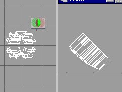
Using the Spline line tool trace out a shape which looks like a gear ,see picture to the left . Select the face of the shape you made and sweep upward . see picture to the left.
Rotat the gear shape 90 degrees , then rotate to match the picture on the right.
Select the object subreact tool and cut away .What you have left is the little shape like on the picture to the left-below.
Reload the command section.

Paint the new gear shape with a rushy brown color.Your model should look like this :

Select a tube shape . rotate it to look like the image on the left. This is the torpedo tube cutout.
Paint the tube with corigated green .
And subtract it from the command section.
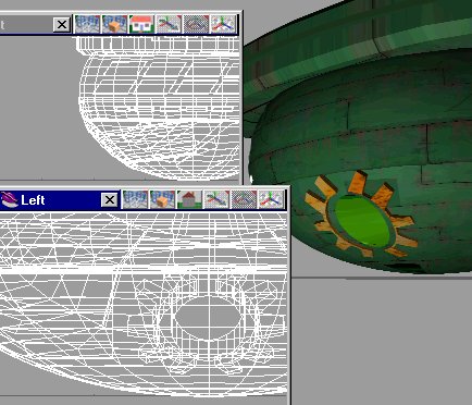
Your image should look like this:
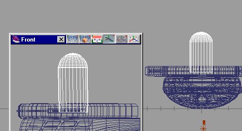
Look right.

Select a ball and a square.We shall cut the ball in half.
Then select the bottem face of the ball .
Stretch the bottem face out as indicated in the image to the right.

Move the stretched half ball to the position as show in the image to the left. Paint it with green panels.
Copy the shape. and strech it wider but shorter.

Move it forward to match the image on the right.
This next think is strange but on the left side only , place a box and stretch it around to match the image on the left.
Do you remember the Disruptors we made and saved .
Load them up again and place one on each side of the command section.
See picture below to the right.

Glue it all together.
Add some local lights and lets take a close look .Your model should look like the image on the left.
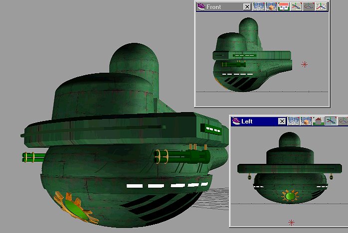
Left click the image for a bigger picture.
Now you have a Command Section , SAVE IT
Do I say that enough?
Next comes Details, things like registry numbers and emblems . That part will be on page five.
Page Five