Areptone Electronic Products
......

Technical Article By Mr. Adeeb Raza
| .............. | Areptone Electronic Products |
...... |
|
Technical Article By Mr. Adeeb Raza |
|
...SOLID STATE VOLTAGE STABLIZER - 1KVA Nowadays Electricity is the basic need of everybody. Nobody can imagine life without electricity because the entire house-hold items from Light, Fan to Television, Computer, DVD, CD Player, Tape recorder, Washing machine, Air-conditioner, Heaters, Water pump, Geyser, Toaster, Mixer Grinder etc., all are useless without proper power supply system. An international standard has already been set for Domestic and Industrial Power supplies system and the entire domestic and international equipment manufacturer follow this standard very strictly. The standard power supply system is 220 Volts 60 HZ 3-Phase for European countries and 440 Volts 50 HZ 3-Phase for Asian countries. It means in Single phase supply system 110 Volts +- 10%, 60 HZ and 220Volts +-10% 50HZ. We all follow the Asian countries standardized system that is 220 Volts +-10% 50HZ. If we look at the voltage variation margin as per the standard supply system we get a variation of minimum of 198 Volt to maximum of 242 Volt. This indicates that there is no need of providing any extra device for protection of household’s items and controlling the power supply system within variation of min 198 Volt to max 242 Volt. This is an ideal condition, which is not possible for India to maintain these norms because of the huge power distribution system with a high distribution losses and industrial/domestic load variation are very common phenomena. The sudden voltage variation from 120 Volts to 280 Volts has been observed to cause damage to costly equipment. To overcome this problem of voltage variation and damage to costly gadgets, one is compelled to provide a voltage control system that is voltage protection device, which is known as voltage stabilizer. For controlling the voltage variation problem different type of voltage stabilizers are readily available in the market. The servo type fully automatic stabilizer with low voltage high voltage cut. The step changer Electro-mechanical relay type voltage stabilizer with hi/low cut the Semi automatic and the rotary switch type manual voltage stabilizers are very common. But they are not suitable for computers; EPABX, PCO monitors and other Microprocessor base electronic equipment, because of the break-in power supply system during step changer. Therefore CVT or UPS are recommended for these equipment, which is very costly with respect to stabilizers. Here is a cheap project for fabricating solid state voltage stabilizer for all-purpose with out using electromechanical relays and without any break-in power supply. The block diagram of solid state voltage stabilizer is given in fig-1. The specialty of this voltage stabilizer is given as follows.
The complete circuit diagram of solid state voltage stabilizer is given following in four parts.
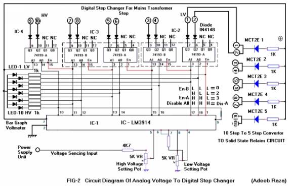
Analog voltage to digital step changerThe circuit diagram of Analog voltage to digital step changer is shown in fig-2. The hart of the solid state voltage stabilizer is design with easily available and very common IC-LM3914. This IC is used as LED type bar graph voltmeter with lover voltage and upper voltage setting by two potentiometers of 5K. This IC senesce Mains voltage and the difference between setting of lover voltage and upper voltage indicate through 10 LED’s in ten steps through Pin no1, 18,17,16,15,14,13,12,11&10. See Fig-2.
All the ten output of 1C-LM3914 fed as input to ICs -74139 Dual 2-bit binary decoder / de-multiplexer. This IC is used for converting analog voltage to digital steps to ensure that only one taping of mains transformer get input supply voltage from Mains. In all condition only one step will be active according to the analog input voltage. Assume first condition that the Mains voltage is less than the lower set value. Then all the output of IC1-LM3914 Pin no1, 18, 17, 16, 15, 14, 13, 12, 11 & 10 will be high. See 1C-2, 74193-A =HHH 74193-B= HHH IC-3 74193-A =HHH 74193-B= HHH AND IC-4 74193-A =HHH causing all the ICs-74193 will be disable and the output will be Nil. & No step selected means low voltage cut off. Assume second condition that the Mains voltage is more than lower set value. Then LED one of Bar graph voltmeter will glow and Pin no.1 of IC1-LM3914 will only be Low and all others will be High. In this condition IC-2, 74193-A will be enable because pin no1 is Low and A0=H, A1=H, means 11=3. This means IC-2, 74193-A Q3 is active this is also step one of step changer and this will ON MCT2E in side diode will glow will fire to Solid State Relay Circuit-1, BT136 Trice will conduct and passing AC to Mains Transformer step no.1 other steps are ideal. Like this in other condition will also work in the same manner for details see the truth table given below See Fig-2A.
The main transformer tapings and number of solid state relays circuit selection will be depend on the voltage range. Suppose the minimum voltage covered is 100 Volts and the maximum Voltage is 300 Volts. The difference is 200 Volts the maximum taping are available 10 means per tape=20 Volts and 10 number of solid state relays circuit. You can also use 5 tapings of 40 volts per tape with 5 number of solid state relays circuits. See circuit diagram fig-2 in details 10 step to 5-step converter circuit. Diode IN4148 has been used to connect two tapes with one MCT2E of solid state relays. Isolated Solid State Power Relay
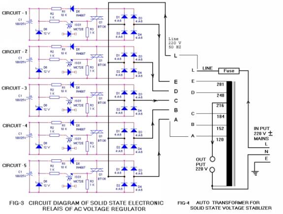
The circuit diagram of Isolated Solid State Power Relay is shown in fig-3. The Opt- Coupler IC MCT2E has been used for controlling the steps and connecting Mains Power Supply to correct voltage to the taping of Power Transformer with Solid State Relay (SSR) formed with bridge of 4 Diodes using 6A4 (Diode 6Amp-400Volts) and a Trice BT136. The capacity of SSR is depend on the both components. Here it is used for 1KW Load. For more than 1KVA and less than 3KVA one can used BT139 with parallel 2- 6A4 (8 diode 6A4 in a bridge) can be used to form a solid state relay of up to 3 KVA Sold State Voltage Stabilizer with 3KVA transformer. Control Power SupplyControl supply circuit diagram is given in FIG-6. The control transformer is a step down transformer primary 250V secondary 14-0-14 500 mA. The secondary 12 V Supply refitted by D1,D2 IN 4007 rectifier and the filtered by a capacitor 1000 MFD 25V .The 3 pin IC-7812 Regulator has used for 12V stabilized power supply for operation of control circuit of solid state voltage stabilizer. The potential divider formed by resistances R1 and R2 1K for input voltage sensing IC-LM3914 for controlling the steps of mains transformer through solid state relays.
Mains Transformer The Mains transformer used here is an AutoTransformer with taping of 120V, 152V, 184V, 216V, 248V and 281V respectively as shown in FIG-4. All the tapings are connected with the voltage control Solid State Relays to provide respective voltage. The tap 216V is connected directly to the Output. You can also design your own transformer as per your requirement as explain following in Fig-5.Details of Auto Transformer
See the transformer design as given following
SETTING OF SOLID STATE VOLTAGE STABLIZERThe total circuit of solid state voltage stabilizer assembled on a general proposes PCB.All the trice BT136 will fix on suitable heat sink with Mica and insulated nut bolt to isolate all trice with each other. First of all, Setting of solid state voltage stabilizer will be done without connecting mains transformer as describe below.
Note: - Male and Female Pin type Power Connector May be used to connect Mains Transformer Taping with solid state relays on PCB. Bar Graph LED Voltmeter connection also provided with Male and Female PCB Pin type Connector from BCB to front Panel of stabilizer.
|