Hi everyone, my name is Luciano, I live in Buenos Aires Argentina. After building
the bike I decided to upload some of the info to a web page. This electric bike
is based on Gordon Wong´s .I totally recommend it: http://gwinfo.dhs.org/ebike01
I have made 127km so far without any problems.
Technical data :
Maximum Speed : 23.4km/h Cruise speed: 18km/h
Autonomy : Aprox. 15km no pedaling.
Batteries : 24V 14A/h ( 4 batteries of 12V 7A/h )
Supposing each battery ( discharged 11.6V máximum charge 12.8V ) :
| Trip |
Mean Speed |
Terrain |
Time |
Battery Voltage |
| 8km |
12.7/h |
flat |
48min. |
12.25 |
| 4.5km |
17km/h |
semi flat |
16min. |
12.55 |
 |
This is the electric bike, the PWM controller and three
of the four batteries are in the inside of a plastic toolbox, while the
battery that´s left is actually on the toolbox. It has two motors,
one of each side, unified by a roller of 4.6cm, which goes against the
wheel.
The motors are 12V, but the batteries are used forming 24V 14A/h. Yet
there seem to be no problems using 24V on these 12V motors. The batteries
are rechargeable gel type.
On the back of the toolbox there is a cooler, taking heat away from the
MOSFET´s and the DIODE, which are mounted on a heatsink.
06/01/03 : I managed to put the 4 batteries in the box, removing the
cooler and placing the half of the dissipator outside.
|
Batteries :
I used 4 Yuasa NP12-7 ( they cost u$S13 each ) rechargeable lead acid. They
rate 12V and 7A/h, and they where found in a broken UPS. The gel type have a
discharge curve associated. If for example, you consume 7A from a 7A/h gel battery,
you will consume it not for an hour but four 33minutes. And if for the same
battery you pull out 14A, they will last only 12minutes. That´s why I
chose 4 batteries to get 14A/h instead of 2 getting only 7Ah. The motors with
no load pulled 7A/h, and the range will by unsatisfying. Doubling the capacity,
increases range always more than double.
Motors :
Two fan blower motors where used ( of a Ford Ranger ), they are 10cm diammeter.
They where connected opposed to each other by a 4.6cm alumminum roller.
Note : the motors have the ground shorted with the chasis,
when you connect the chasis electrically with the roller, you can not use them
in parallel ( be careful ). To connect them in parallel and not in series (
more power and speed ), you need to open the back cover and aislate the connection
with the chasis ( you´ll see a copper plate touching the chasis and the
metal cover itself). Please verify with an ohmeter.
 |
The roller goes against the wheel, between 0.5 an 1cm.
The more you get it in the wheel, more torque, and more power you consume.
The less you put it in, less torque ( you´ll notice and slipeage
when you climb a hill ), but the range will increase.
|
This fan blower motors are 12V, 1150RPM, and each one consumes 3.5A/h with
no load. Other have 3600RPM, and this changes the roller diammeter. In Gordon
Wong´s bike, which uses an EV Warrior motor, the roller diammeter is 3cm
( by the way it is still in Meci at U$S40, and in ebay you can find a 24V 5A
charger at u$S20 ).
The roller against the wheel is the easiest system of
them all, but you lose power in the friction. They pulley and strap system are
best, but they are difficult to build, and they must have a reduction.
PWM controller :
It has two 2 LM555P ( u$S0.30 each ), 1 LM311 ( u$S0.80
), 2 IRFZ44N ( u$S 1 each), a cooler found in a broken PC ( 12V 0.12A/h ), and
a heatsink from the same UPS I found the batteries.
The circuit is the following.
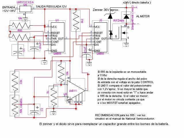
The first 555 is a monostable at 11Khz ( I suggest using between 10 and 20Khz
), it then feeds other 555 in astable mode, the width of the pulse is controlled
by a voltage regulated with a pot. The LM311 is used to compare this voltage
with aprox. 1V, when it is above, the reset of the 555 goes to "1"
and the pulses get to the gate of the MOSFET. This is used the get the motors
stopped, and to avoid scratchy sounds while turning them on.
I blowed the MOSFET´s a couple of times, but each time I learned something
of it. The first thing I learned was that the ground and the chasis of the motors
where connected electrically. Hume and fire came out of the fan. Also the 555
and the 7812 where blown. I suggest not connecting the cooller to the 7812 circuit,
because it get´s hot and it finally breaks the rest of the circuit. The
way I have it connected now, it with 2 15V 1Watt zenner in parallel, directly
to 24V. Now the 7812 is not hot anymore. The blown MOSFET photo is the following
( RIP ):
 |
Note : The MOSFET drain is generally
connected to the case, beware then of the DIODE because all the cases
can´t be connected electrically. Stick the diode and the 7812 to
the heatsink and put a piece of cloth and don´t screw them to the
heatsink.
Use the case to connect to the MOSFET drain, you´ll
save cables and future problems if you need to replace them. |
Looking at the MOSFET from left to right ( GATE, DRAIN, SOURCE ), but I insist,
use the case to connect to the drain.
The MOSFET I chose is the IRFZ44N, about a dolar each, and I used two in parallel
( Gate and Gate, Drain and Drain, Source and Source ). The IRFZ44N rates 60V
and 50A DC ( 120A peak ), with an Rds(on) about 0.024ohm. The pdf with the details
is :IRFZ44N. It will dissipate 60W at 50A continuous.
But the consumption of the bike if around 7-14A/h aprox.
DIODE : I used the MBR2040 ( 20A40V). As the motors are inductive, when you
take away current ( on off PWM ), they still have some power on the inductors,
which need to "flyback" with a diode. I have also read to can use
a MOSFET with Gate and Drain shorted, and with this you automatically get regenerative
braking.
02/01/03 : I replaced the diode with a MOSFET, shorting the gate with de source.
I can see an autonomy gain of 30%. To gain regenerative braking you need to
turn on the "diode" MOSFET when the drive MOSFET is OFF. But I have
to think it for a while, you can´t have both MOSFET ON at the same time
cause the battery will be shorted.
6/01/03 : Between gate and battery ( + ), I connected a common diode and 2
13V 1W zenner in series. If the motor generates a 40V spike,
the drive MOSFET will be turned ON. This replaces a main capacitor between battery
leads.
 |
Here is the heatink with the MOSFET´s, and the big
DIODE stuck with the cloth. The circuit was built with an standard card.
In my next project I promise myself not to use so many wires.
|
Mounting the circuit:
 |
A plastic toolbox of less than u$S1.5 was used, and in it
I mounted the circuit, heasink, cooler and three batteries. The fourth battery
is actually outside the toolbox. An elastic rope was used to "hug"
the toolbox to the bike. |
Throttle :
 |
The pot was put in a film can, and the a plastic support of a bike´s
rear light was used. The other thing you can see is a solar light. I wish
the bike was solar, but solar can only be used to charge batteries in day,
otherwise the panels would be bigger than the bike. |
 For suggestions, questions or exchange of opinions or material on Electric Vehicles please contact :

Luciano trentino123@hotpop.com