Automotive Tech
 AEM V2 Install
The AEM V2 is what is referred to as a "cold air intake", or CAI, because it draws its air from a source outside of the hot engine compartment. Cold air is desireable because it is more dense than hot air, resulting in an increase in horsepower.
The disadvantage of a CAI is that they typically situate the filter in a low position on the car, which can be a problem if the car is driven through water that is deep enough to submerge the cone filter. Ingesting water into the intake tract may result in water getting into the combustion chamber, and if enough gets in there the lack of compressability of the water (vs. the air/fuel mixture that is supposed to be there) will damage the engine. On some lowered cars the cone filter of the CAI is very close to the ground, so the potential for problems in increased. That said, it would take a pretty deep puddle to submerge the cone filter, and those running a CAI of this type should obviously avoid any puddles that look deep enough to cause trouble.
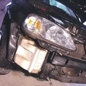
For the 1999 and 2000 Civic SiR, the AEM V2 draws its air from the passenger side of the car, behind the bumper cover, in front of the fender liner, where the stock resonator for the intake tract would be. Image to the left shows the stock resonator after the bumper cover has been removed. The AEM instructions do not ask for the bumper cover to be removed, but it is easy enough to do and it makes the job far easier if you do. See bumper cover and resonator removal page for more info on how to remove the bumper cover.
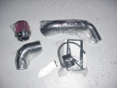
The AEM V2 comes with everything you need for the install (well, it is supposed to, anyway. See below), including hose to re-route the coolant line from the engine block to the throttle body, and a replacement engine mount that allows the big fat intake tubing to pass through into the spot where the filter goes.
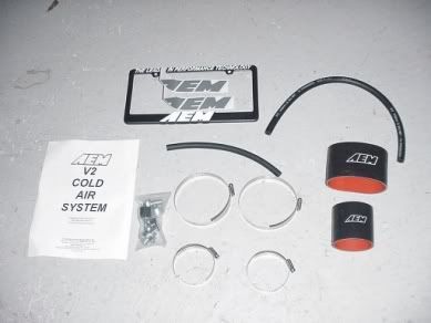
There is even a license plate frame and a couple of AEM stickers included for that extra 15-20 horsepower that stickers tend to give (see also: http://bezean.20megsfree.com/stickers.html, sorry about the popups). The instructions are reasonably complete, and include black and white photos for most of the steps.
Because the instructions do a reasonable job of describing the install, I will skip over the basics that are covered by the instructions and try to concentrate on the things that the instructions overlook, or problem areas that I encountered during my particular install.
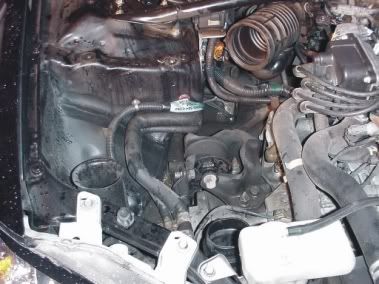
The first steps involve removal of the stock airbox, intake tubing, and resonator. On the Civic Si/SiR there is a breather tube from the valve cover to the intake tube just upstream of the throttle body (aka TB) and an Intake Air Temperature sensor (IAT) right beside it.
The breather tube from the valve cover starts out as a rubber hose, then joins into a "hard line" that is basically bent metal tubing, then turns into another rubber line before attaching to the stock intake piping. The hard line is attached to another hard line that is part of the coolant line from the engine block to the TB (this keeps the TB from icing up by warming it with hot engine coolant).
For the AEM and other aftermarket intake setups, the hard line is removed to allow easier fitting, but this means that not only does the breather tube from the valve cover need to be replaced, but the coolant line to the TB must also be replaced because the hard lines are attached. In the AEM V2 kit, both replacement lines are provided, and the stock clamps for the coolant line are re-used.
The connector for the IAT sensor is easy enough to undo, just be careful with it because I'm sure if you break it it would cost about a bazillion dollars to replace...
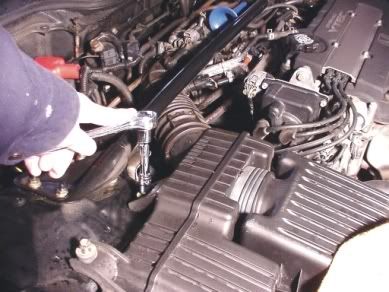
I found it easiest to take the airbox out seperate from the intake tube, which might be the only way it will come out anyway without having to remove the strut tower brace. The airbox is held in with two bolts (see image above), and is just pushed into the intake tube. Also, the tube that goes into the bottom of the airbox from the resonator is just pushed into the airbox, so it takes a bit of pulling to pull the airbox out once the two bolts and tube to the TB are undone.
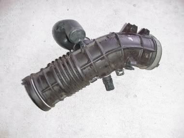
Once the airbox and and tubes/wires to the intake tube are off, the intake tube comes off by loosening the clamp at the TB. The intake tube has three or four rubber "clamps" that hold various wires. The wires can be just gently pulled out before pulling the intake tube out. Be careful, as one of the clamps in on the underside of the tube and I did not notice it until I tried to yank the tube free - no damage but if I had yanked hard enough there might have been.
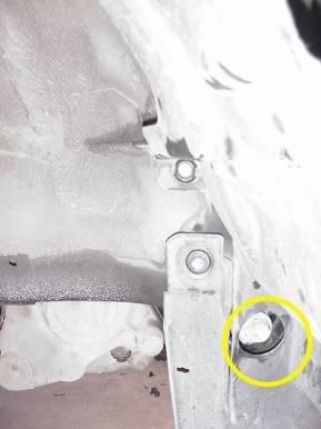
The most difficult part of my particular install was the replacement of the stock lower passenger side engine mount bracket with the one provided by AEM. The stock engine mount bracket is made from two halves of pressed steel welded together in a shell structure which is likely the lightest and strongest way to make such a part cost effectively. However, the space that it takes up is right where the big fat tubing of the V2 needs to go on its way behind the bumper cover. Thus, AEM provides a replacement engine mount bracket that is just a big hunk of flat bar bent and drilled for mounting holes.
Removing the stock bracket was not a problem, just remove the nut circled in the image to the left, then remove three bolts that secure the bracket to the engine. The hard part was getting the big bolt (shown below) out of the stock bracket that is re-used in the AEM bracket. I did not have a big enough vice at my disposal at home, so I tried standing on the bracket and using an impact driver, to no avail. I finally got it off by using a frined's big-ass vice and heating the bracket a bit with a torch.
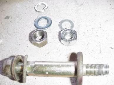
But getting the bolt out of the stock bracket was only the beginnings of my problems with this mount. After getting the bolt out, I put it in place in the AEM bracket and threaded the washer and nylock nut that AEM supplies onto the end of the bolt and tried to tighten it on. After a few turns, I realized that the nut is not going any further on the bolt, so I backed it off to find the threads on the end of the bolt were stripped. Turns out that the nylock nut that AEM supplied had a coarse thread - the bolt has fine threads (12mm, to be exact). AEM supplied the wrong nut, and now I have nothing to secure the bolt, so I can't install the mount, so I can't finish the install and drive to work on Monday. Doh!
A frantic search for a 12mm fine thread nut at Home Depot and Canadian Tire was unsuccesful, and this being Sunday, none of the industrial fastener warehouses were open. This was obviously a big problem. In desparation, I checked out the local Home Hardware, and they had an Imperial fine thread nut that had the same threads, but was a bit big, so it had play when threaded on (in the image the Imperial nut is on the left, with the AEM supplied incorrect nut on the right). Well, with no other options, I put the Imperial nut with a split lockwasher and flat washer on as a band-aid until I can get the correct nut.**
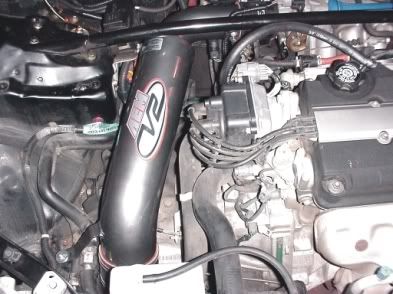
The fit of the unit is a bit tight in spots. The Canadian SiR differs from the US Si in really only once significant way: ABS. In the image to the left, you can just see the ABS relays perched on a metal bracket bolted to the side of the strut tower, just behind the strut tower brace. The clearance between the bracket and the V2 is minimal. I carefully bent the bracket just a tiny bit to give the V2 a little extra breathing space in this area.
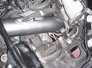
Also, where the filter sits in the fenderwell, the part of the plastic fender liner that comprises the floor of this chamber pushes right up against the filter. The plastic is very flexible, so I can't see any potential for damage or problems, but the fit here, too, is very tight. Removal or trimming of the plastic would be inviting disaster in the form of water ingestion or damage to the filter from a direct hit from debris.
The bracket that is welded to the side of the V2 that engages a rubber mount that AEM supplies did not line up at first. A little flexing and bending of the mount allowed the bracket to fit, but the bending caused the paint on the bracket to crack a bit. I will be touching up this crack to avoid corrosion. Also, the rubber mount that AEM supplies threads into an existing threaded hole in the engine compartment. On my vehicle, the threads in the hole were full of paint and/or dirt. I had to use a tap to clean up the threads before mounting the rubber mount.
The mounting problems aside, the kit is a good fit and AEM provides each and every part that you need to mount the system. I have been in contact with AEM through their website and they assure me the correct nut is being sent to me at this time. On many lower priced intake systems, brackets need to be fabricated, extra breather tube holes need to be plugged up (or worse, drilled), and/or breather hoses must be sourced. This was the type of situation I was trying to avoid when I purchased the V2, and I think the results are definitely worth it.
 A few quick runs with the G-Tech showed some minor gains in peak horsepower, although before and after testing was not done under comparable conditions. But in the raw, the car was showing 135 to 137 horsepower when I tested it in dry conditions in July, running on Toyo T1-S tires. Right after installing the V2, it put out 140 horsepower in wet/raining conditions and running Nokian NRW snow tires (very limited traction). I am guessing the peak power gains are in the 5 to 8 horsepower range minimum. Not spectacular, but reasonable IMO. When combined with an enlarged collector, Carsound cat, and stainless free-flowing exhaust system, the total package nets a 16 horsepower gain over stock.
What is more interesting is the sound the car now makes. Under light throttle conditions, the sound is virtually the same as stock. However, under full throttle, the tone is now much lower and louder, and when VTEC engages the higher lift cam lobes, the tone volume immediately goes up sharply, like turning on a light switch.
One of the claims of the V2 system over other CAI systems is a spread of good horsepower gains accross the rev range, and after a few days of commuting with the system in place, the Assomometer (aka Butt Dyno) reads "no power losses and potential power gains in the midrange". Translated, that means I did not lose any power through the midrange (as I was afraid I might), and the optimist in me thinks there might even be some power gains, although the increased noise may be skewing the Assomometer results, as can sometimes happen (I hear more noise, so I must be making more power!).
 Many thanks to Kensai Racing for their support of the HADA Motorsport Club and its members.
**Update 03/11/02
I was able to get in contact with AEM through their website, and they sent the correct nylock nut immediately. I am very pleased with the service, and they covered the error no questions asked. A++
 **Update 04/02/08
Because I installed the V2 as a replacement for a broken stock airbox, I run the V2 all winter long. There has been a considerable amount of snow and slush around the GTA this winter, and the filter has gotten quite dirty as a result (see photo - click image to view larger image).
It warmed up a bit this weekend, so I took the opportunity to remove the bumper cover, remove the filter, and clean and re-oil it using a K&N cleaning and oiling kit (the AEM filter is a K&N cone filter with an AEM logo on the end).
Beware - if you run this or a similar CAI setup in the winter in areas where it snows, the filter will get wet and dirty. Keeping the filter well oiled, and cleaning it once or twice over the course of the winter will help protect the engine, but for best results do not run this type of CAI setup in snowy and slushy conditions.
)


 A few quick runs with the G-Tech showed some minor gains in peak horsepower, although before and after testing was not done under comparable conditions. But in the raw, the car was showing 135 to 137 horsepower when I tested it in dry conditions in July, running on Toyo T1-S tires. Right after installing the V2, it put out 140 horsepower in wet/raining conditions and running Nokian NRW snow tires (very limited traction). I am guessing the peak power gains are in the 5 to 8 horsepower range minimum. Not spectacular, but reasonable IMO. When combined with an enlarged collector, Carsound cat, and stainless free-flowing exhaust system, the total package nets a 16 horsepower gain over stock.
)
