| Hardware to Communicate Between Computer and ICOM Radios | |
My URL: http://uk.oocities.com/blakkekatte/
|
Looking for hardware to communicate with your receiver? A hardware interface is needed beween computer and radio. One of the main functions is to manage the voltage differences between the RS232 serial port on the computer (where voltages can be up to + or - 25 Volts) and the very low transistor logic levels (up to 5 volts) inside the radio. You need to know what you are doing if you are building a hardware interface, otherwise you may damage your radio. These schematics and plans are offered as resources. I do not guarantee them. If you build them, then you take the responsibility. The CI-V System ICOM's own manual (2.76Mb) describing the protocol used. The current ICOM standard system for communication between computer and radio is called the ICOM Computer Interface Version 5. This is commonly called the CI-V interface standard. The CI-V system allows for a computer to communicate, through it's serial communications port, to an Icom radio. In its full implementation, the CI-V system allows up multiple radios to be controlled from the same cable and computer interface. Icom has developed the CT-17 interface to allow up to four radios to be connected to one computer. Cloning uses the same protocol, but it is assumed that there will only be one radio communicating with one computer (or two radios communicating with each other) and the interface hardware can be simpler. Often the hardware is installed inside the plug for connection to the computer, with the hardware drawing its power from the computer's serial port. Icom has developed the OPC-478 interface for cloning from a computer. It helps if you know that the hardware to clone an ICOM radio is almost the same as the hardware used to control an ICOM radio. Only the wiring of the plug that connects to the radio is different. The 'cloning' hardware plugs into the speaker outlet. The control hardware plugs into a dedicated CI-V data socket. See the difference What the Hardware Does. The document How ICOM Cloning Works gives some background to the hardware issues, and summarises what can be found in these pages. The Icom CT-17 interface is based on the Maxim Max232 RS-232 Line Driver/Receiver (443kb). The following block diagram of the CT-17 interface shows how the RS-232 and TTL voltages are matched together, and shows the flow of data through the device. |

|
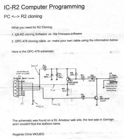
This diagram clearly shows how data transmitted from the computer is reflected back to the computer for monitoring of the transmission. The diagram also shows that radio data is also reflected back to the radio so that collisions can be detected. Because the transmit-data line and the receive-data line are connected together, the CI-V interface is connected in a wire-OR configuration. When the computer transmits a command, the command is automatically echoed back as received data, followed by the radio's response to the command, if any. For example, if an eleven-byte command is transmitted to a device on the cable, and a six-byte response is sent, the computer will receive a total of seventeen bytes (11+6=17). This configuration allows devices on the cable to monitor their own transmissions in order to detect interface collisions. A collision occurs when two or more devices transmit simultaneously. If a collision occurs, the command must be re-transmitted. The radio or computer that is transmitting reads its own transmissions back from the communications cable. If it detects that another device has transmitted at the same time (i.e. there has been a collision) the radio or computer stops transmitting, listens to make sure that there are no other data transmissions on the cable, transmits a jamming code (5 characters of value $FC), and retransmits the original command. Icom CT-17 Interface. The CT-17 interface was designed by ICOM for computer control of Icom equipment and is based on the MAX-232 chip. This interface allows up to four devices to be controlled by one computer. Icom OPC-478 Interface. The ICOM design for the OPC-478 interface is a simple transistor circuit used for cloning. The version by Chris VK3JEG gives equivalents for the transistor and diode parts. That version is the one commonly found on the internet. However the one from ICOM Japan's site has a few modifications. I have added the transistor and diode equivalences from VK3JEG's copy of the earlier version of the interface. WA0SXV has some reservations that this design might not properly implement the RS-232 protocol. Other CI-V Designs on the Internet. The Rolls-Royce of other interface designs (1.5Mb) is the one from the ARRL Handbook. It has buffering to protect the radio. The article also contains a very good explanation of the RS232 serial port issues, and gives a good understanding of what is going on electrically. The printed circuit board for this circuit can be found at the ARRL site. WA0SXV has some comments on improving this design. At the other end of the scale is this very simple interface based on the Max233 chip and which uses only 2 electronic components. Using YAESU Interface Cables Dave Martindale in a posting to the ICOM IC-R2 discussion group and a subsequent posting points out that the Yaesu ADMS cable for their scanner can be converted for use by ICOM radios. The schematic for the Yaesu cable can be found here. Other Hardware Links Ekki DF4OR has a CI-V hardware page. |
|
Copyright © 2000 Yahoo! Inc. All rights reserved. |