|
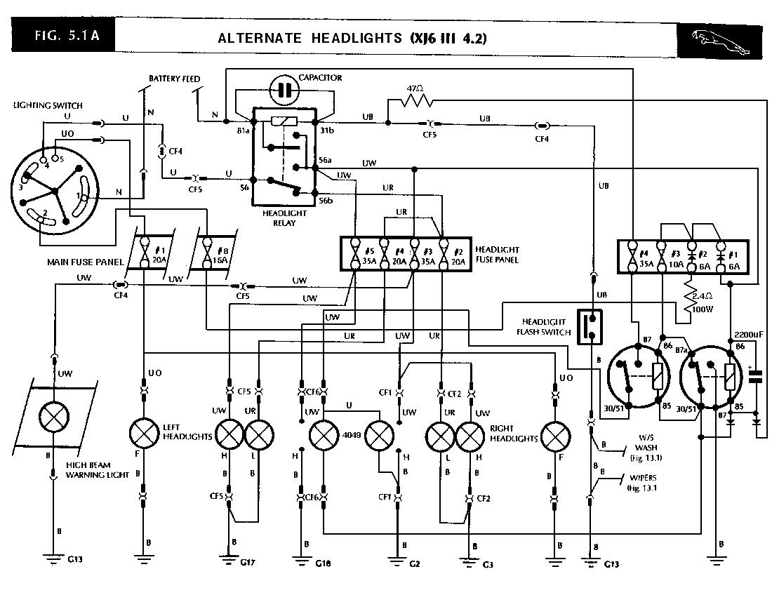
Top Incendiary BeamsAfter installing the original Lucas 7" headlights in my 1983 Jaguar XJ6 Series III, I got overtaken by the interesting effects of the pilot lights in the headlamp assemblies. I wanted to do the same to the 5 1/4" high beam units!In my past life I had a FIAT 124 with 7" Amplilux lights (H4+H3), with inboard aircraft landing lights (225W). Without a doubt, an excellent system for my rally driving pursuits of a younger self. I was hoping to go that route, but discovered that the Marchal Amplilux were no longer being shipped to the US from France, and were now only being sold by the Ferrari dealer for $500/each. Salvaging my pride while brushing against a $90000 1974 Ferrari Dino, I decided to only take the aircraft landing lights from this dream. I ordered a set of Philips Automotive 4049 165W (at 13V, I measured 200W at 14.2V) sealed high beam units from JC Whitney ($14.95/each + shipping, A local Pep Boys sold the 4049 bulb as a replacement for a handheld spot light for 19.95/each) and started planning a circuit to run the bulbs at 10W/each(Pilot), 35W/each(High Beam) and 165W/each (Incendiary Beam). The 4049 is an exact mechanical replacement for a regular high beam bulb down to the notches, minus the connector (the 4049 uses screw terminals to prevent effortless installation for the neophytes). The bulbs were not as powerful as the aircraft landing lights, but have the same pencil beam focus. The clear unobstructed lens adds some additional daylight shine for the front of the Jaguar. The circuit used is outlined as an overlay on the original Jaguar Electrical diagrams in Publication S 57 (Contact Jaguar Service 708-331-9151, $25 + shipping). The Schematic and Layout diagrams are shown in the context of the entire headlamp and Foglight wiring. You will need to refer to the originals to discover what I added to the headlamp circuits if it is not readily apparent. The slightly ambitious circuit works as follows. In park and low beam, the 4049 lamps glow a haunting Redish Orange as additional pilot lights. With a quick flash to high beam, the 4049's glow a Bright Orange that matches the apparent brightness of the original 45W sealed beam units. If you opted to hold the high beam flash arm for a second instead, the 4049's go to full brightness. Beware, stop signs two blocks away may blind you with the reflections, so this `mode' is only used on dark highways. My wife was reticent to support my venture into adding these lights to the car, but now finds them to be quite useful dealing with the county's lack of street lighting, carefully utilized only during her late night shift. I purchased the 70A light relay from JC Whitney ($9.95 + shipping) as well, but found out later that a local Army Surplus Electronics (Starcraft) place had most of the components I needed. I spent an hour selecting a perfect 3.3 ohm 100W variable power resistor to experiment with, and determined that I liked the brightness of the bulbs in series with this resistor set to 2.4 ohms. I expect the bulbs will last indefinitely at this low power level. The regular `high beam' brightness was accomplished by letting the bulbs operate in series (but without the 2.4 ohm resistor), fed by the power and fuse of the regular high beam switch. The Incendiary mode switches the bulbs into parallel wiring, using the above mentioned 70A relay (chosen for low voltage drop, the bulbs only draw about 30A). Another 30A relay controls one `leg' of the 4049's, it is the Jaguar original Fan Relay (DPST), used to switch the resistor or regular high beam power off and ground the leg in preparation for the parallel wiring (see schematic). The delay circuit was simplicity itself, two small diodes, feeding an RC delay, a 2200uF capacitor across the coil of the `primary' relay (the 70A relay coil was slaved off the contacts of this primary relay to keep it out of the delay circuit), and a 47 ohm resistor connected to the high beam trigger circuit. The hardest part of the project was acquiring a connection to Fuse 8 of the main fuse box. I fished a wire to the vicinity (an issue in itself since the hood release mechanism cables actually go through a body cavity, so must feed a stiff snake), then detached the fuse box and the protective insulators, then soldered the wire directly to the fuse connector carefully to ensure that the fuse clip did not melt through the main fuse box body. I expect that soldering will be appropriate since this part of the circuit only has about 3.5A flowing through it. I needed to do this to prevent affecting the bulb warning units that check the park lights. A less ambitious person may decide to just buy the bulbs and a 70A relay to drive them and call it a day, but I felt this was not an option since it may prevent the use of the high beams due to their severity. One could also par down the circuit somewhat if utilizing a separate switch to enable the parallel wiring of the 4049's, rather than using the delay circuit. In any case, the 4049's do give the older cars with 5" high beam units an extra lease on life by competing with the other fog light boneheads with PIAA, Quartz, Blue Diamond, 100W 9004's or other such nonsense :-). You will notice in the wiring diagram the addition of the fog lights to the circuit. To enable the fog light switch, you remove the small plastic bezel from in front of the light switch. Remove the light switch knob. You will notice a small circlip on the shaft that rests against the body of the light switch. Pry the circlip off. Once this is performed, the knob can be pushed in and turned to the foglight setting. The bullet connectors that lead to the lamps are ready to go underneath the bumper. OBJDisclaimer: The 4049's are probably not legal (in parallel wiring) for road use, so please use them responsibly. I do not support their use as a weapon. I expect that the average Jaguar enthusiast is of the same mind. Parts List (with approximate price): 2 Phillips 4049 Automotive high beams ($20/each) 1 40Amp or greater SPST relay ($10/each). 1 30A DPST relay ($11/each, $3.50/each surplus) 1 2.4 ohm 100W resistor ($3/each surplus) 2 6Amp or greater rectifiers ($2/pair) __(I mounted them on fuse clips). 2 1Amp 1N4000 series rectifiers ($0.60, RS276-1653 $2.79/25) 1 1/4W or greater 47 ohm resistor ($0.05) __(may have to tune to the DPST relay coil). 1 2200uF 25Volt or greater electrolytic capacitor ($2) 1 35A fuse ($1) 1 10A fuse ($1) 1 4 position fuse holder ($2) __(two fuses, two high current rectifiers) Spade connectors, bullet connectors, splices, color coded wire, crimpers, soldering iron etc.
Top BLG switch wiper failureMy wiper return switch has gone intermittent. No duh, the wiper circuit carries considerable current for the wiper switch to endure. In addition, the wipe action is necessarily slow due to the long lead lengths used to service this circuit.I added an 8 diode, two relay circuit situated near the wiper motor. I guess you could call this a `wiper amplifier' since it handles the current to the wiper motor, but with the perk of dealing with the `BLG' wire failure that the wiper switch suffers from in old age. I soldered the 8 diodes directly to the spade slip ons so that they did not take up any real space, so the whole circuit could be assembled on a bracket and not be an issue for the space that resides between the battery and the wiper motor. The circuit used is outlined as an overlay on the original Jaguar Electrical diagrams in Publication S 57 (Contact Jaguar Service 708-331-9151, $25 + shipping). The circuit Schematic shows the resultant wiring diagram. Six of the diodes are used to detect when the wiper electrics should be active, turning on the main relay when the column wiper switch is active, or the run switch in the wiper motor is active. Two diodes are used to deal with the reverse voltage spike that occurs with the relay turning off. The other relay is used to switch between the slow and the fast windings of the wiper motor. The inline fuse power passes directly to the common point of the motor, the relays supply grounding action to perform their duties. The four wires to the motor are KLG (Pink Light Green Stripe) to pin 1, OLG (Orange Light Green Stripe) to pin 2, WLG (White Light Green Stripe) to pin 3 and BLG (Black Light Green Stripe) to pin 5. The OLG wire actually does not need to be cut, just tapped, this wire is optional since it is the actual tap that is used to detect and deal with the BLG wire failure indirectly by taking action from the wiper motor park/run switch instead. Pin 4 remains untouched as the Black wire to the common ground point. I wedged the circuit between the battery and the wiper motor in the end, and ran the positive lead to the firewall post, and the ground lead to a convenient bolt holding an Air Flow Meter electronic device on the inside wing (beware, the bolts that hold such have nuts on the other side that are not captivated). Note: In the schematic, the wiring reverses the fast and slow settings such that intermitent runs fast, fast runs slow, and slow runs fast. The schematic is used to record exactly what changes I have made to the the vehicle in my case, which may differ from what others may decide to use of this modification. The BLG and WLG wires can be reversed for the traditional behavior, trust me ... ;-> Parts List (with approximate price): 2 30A DPST relay ($11/each, $3.50 at army surplus) 8 1Amp 1N4000 series rectifiers ($0.60, RS276-1653 $2.79/25) 1 35A fuse ($1) 1 Inline fuse holder ($2) Spade connectors, bullet connectors, splices, color coded wire, crimpers, soldering iron etc. |


