Send comments or questions to Scott
![]()
For about the past year now, I've become very interested in upgrading my existing stereo setup. Well, let's just say that like most of my other hobbies, I've gone overboard! What started out as the desire to build a small pair of 2-way speakers has turned into a fairly big project.
Part of this involves going to a bi-amped system, with an active crossover handling the duties between my BESL Series 2.4 MTM monitors, and my BESL Single CSX-10 bass modules. Marchand to the rescue!
I ordered the Marchand XM9-KK (2-way version) kit back in May '99, and opened it up.
 |
 |
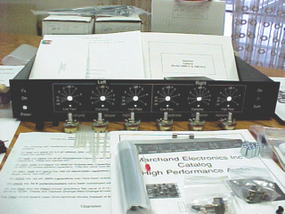
The first thing that struck me about this kit is the quality of the components used throughout. The unit actually is fairly heavy due to the very strong steel chassis. The paint job and silkscreening on the chassis are first-rate.
![]()
 |
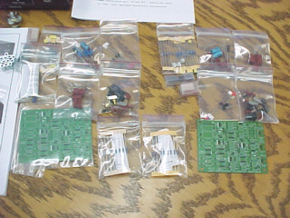 |
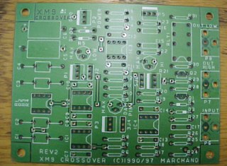
The printed circuit boards for the crossovers are excellent. They are double-sided with plated thru holes and a soldermask. The boards are also silk-screened for easy assembly. On the right are the two crossover pcboards and their associated bags-o-parts. It takes two crossover boards for a 2-way, 2-channel system (bi-amped). It takes four pcboards for a 3-way, 2-channel system (tri-amped).
After a few months hiatus from the XM-9 kit (I was busy building the monitors and sub modules), I began construction of the kit. The directions are straight forward and easy to understand. The excellent markings on the PCBoards really aided in assembly. I assembled the 2 crossover boards first, and then the power supply board. After the boards are complete, it's time to work on the chassis and it's associated wiring. This was a little tedious, but not hard at all. I figure it took me about 20 hours to complete the kit, taking alot of breaks along the way, not to mention double-checking everything.
Once the chassis is completed, the power supply PCBoards can be mounted and tested. Believe it or not, it worked the first time! There are two red LED's on the power supply board that will light if everything's ok. From this point, it's just a matter of installing the crossover boards and hooking up the wiring harnesses.
![]()
 |
 |
The completed PCBoard on the left is the power supply, the one on the right is one of the crossover boards. See the 4 little (blue) resistors on the left side of the crossover board? That's the frequency module that sets the crossover point for the board. The ones I have installed at this time are 100Hz. The resistors are soldered across an IC header, and plugged into a socket on the board. To change the crossover frequency, just pop out the module and insert a different one!
![]()
 |
 |
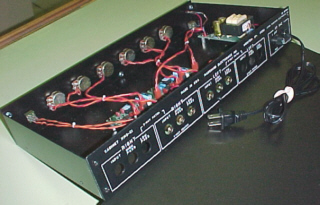
You can see in these 2 shots the internal wiring to the pots, as well as the board layout inside the chassis.
One cool thing about this kit is it's flexibility. Even after it's completed, this kit is upgradable to a 3-way version. Just add 2 more crossover boards, swap out the front panel, add 6 more pots and you're in business!
![]()
 |
 |
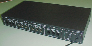
Here's a couple of shots of the rear of the unit. The rear panel is ready for expansion by providing outlets for two additional crossover boards. The right-angle phono jacks are soldered directly onto the crossover boards, and protrude out the access hole in the back. I believe in the "deluxe" kit, the phono jacks are of the screw type, and attach directly to the panel.
![]()
 |
 |
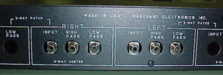
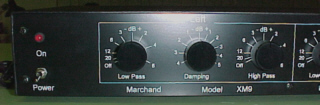
Here is the left and right sides of the front panel. The power switch is on the left. The Sum switch is on the right (combines both low-pass channels for feeding a single sub).
![]()
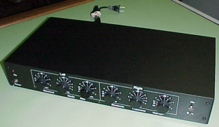 |
Here's the completed unit. I am really pleased with the quality, sound, and flexibility this unit has added to my system. Thanks to Phil Marchand for offering us Audio junkies components like this!
![]()