 |
 |
 |
 |
 |
 |
 |
 |
 |
 |
 |
 |
 |
 |
 |
 |
 |
 |
 |
 |
 |
 |
 |
 |
 |
 |
 |
 |
 |
 |
 |
 |
 |
 |
 |
 |
 |
 |
 |
 |
 |
 |
 |
 |
 |
 |
 |
 |
 |
 |
 |
 |
 |
 |
 |
 |
 |
 |
 |
 |
 |
 |
 |
 |
 |
 |
 |
 |
 |
 |
 |
 |
 |
 |
 |
|
|
Linking Parallel Neurons |
|
|
|
In general, most BEAM circuits are based on Nervous Neurons (Nv) being connected together in series with each other. This technique is the basis of the commonly used micro-core and bicore devices found in most BEAM robots. |
|
|
|
Thanks to the many creative minds developing and using these little circuits, many fascinating critters have been constructed,having some interesting behaviors and capabilities. But what if we did things a little differently. |
|
|
|
This article, on the other hand, is about cross linking the basic Nv (nervous) and/or Nu (neural) neurons. Connecting them sideways, or in parallel if you will.
This should make possible the development of creatures that have increased decision-making ability without resorting to methods or devices that do not mimic nature in some manor. |
|
|
|
Throughout this paper the typical values can be assumed for all Nv and Nu components unless noted. |
|
|
|
Concept |
|
|
|
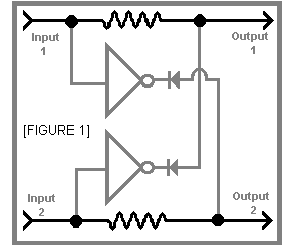
Figure 1 is an example of what I am referring to when I say linking in parallel. For simplification, I have not shown the neuron's own normal capacitors or resistors in this schematic. |
|
|
|
 |
|
|
|
Basically the inputs of each branch is tied to a resistor (to limit cross current) and an inverter. The resistors should only be about 1k so that they do not have a significant impact on the function of the neuron.
The output of the inverter of one branch is connected through a diode to the other branch. It is tied in after the limiting resister of that branch. The diodes are present so that the influence of each branch on the other is inhibitory. Any common type of diode such as the 1N4148 or 1N4004 can be used. |
|
|
|
It is also possible to use the outputs of the neurons instead of using separate inverters, but this will have a very different effect on the way the neurons respond to being linked together. |
|
|
|
X-OR |
|
|
The use of X-OR ( exclusive - or ) gates is frowned upon by most in the Beam community. This is because there are no neurons that have equivalent behavior found in biology.
However there are some situations that require, or at least would be greatly simplified by, the use of such a gate. We therefore need to do what nature does. We need interconnections between two or more neurons to produce an X-OR effect. |
|
|
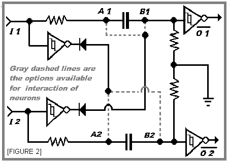
| Figure 2 is an example of such a coupling of neural circuits. In this particular arrangement, two Nv's are tied together to create an X-OR response to simultaneous triggering of their inputs. |
|
|
|
 |
|
|
|
If the input of either branch goes high then the output of the inverter tied to that branch goes low. This low being tied to the other branch will either
absorb or pause the activity on that branch.
If both inputs are low, of course neither neuron fires. If both inputs are high then due to each branch being linked to, and inhibited by the other, again neither neuron can fire. If however, one and only one branch has a high on its input then that neuron and only that neuron will fire. |
|
|
|
There are a couple options available in the way that the neurons can be linked together. The first is linking from the input invertor of one neuron to point "A" of the other. This will cause any activity of the second neuron to pause while the link is pulled low by the first neuron. In the event that one of the neurons was already firing at the time that the other is triggered the firing of the first one would be halted and reset. |
|
|
|
The second option for linking the two Nv's is to tie into point"B". In this case though, there is a different reaction.When a neuron is triggered any activity on the other neuron while the link is low is absorbed by the other thereby preventing it from firing until the input of both go low and it is triggered again. In the event that one of the neurons was already firing at the time that the other is triggered the firing of the first is halted and the activity on both would be absorbed. |
|
|
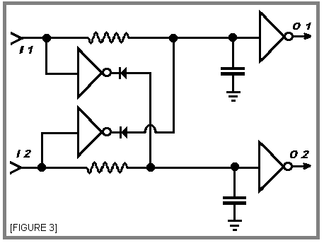
| Next in figure 3 you see a similar arrangement for a pair of Nu's. In this case there is only one tie in point for each neuron. A high at the input of either Nu will prevent the other from triggering. |
|
|
|
 |
|
|
These are the two types of X-OR functions that can be carried out by Nv's. The best part is that it is similar to the type of parallel interaction found in biological neurons. |
|
|
|
If one of the neurons has already triggered when the other neuron's input goes high, the first Nu will be reset and neither will be able to fire until the other's input goes low. |
|
|
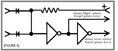
We now have three different ways to perform an X-OR decision. But what if you only want a single output from the two neurons?
Simple enough. Just feed the outputs of the two neurons into an "AND" gate or the circuit shown in figure 4 and you're all set. |
|
|
|
 |
|
|
|
 |
|
|
|
|
|
First Come... |
|
|
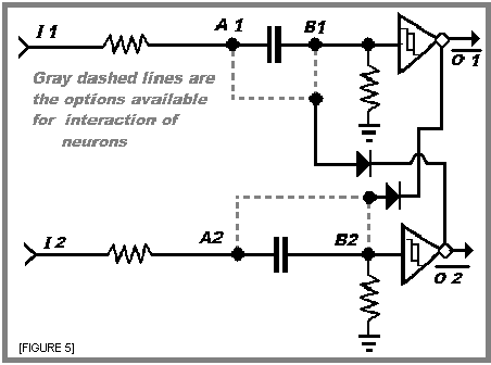
| The following is what I call a First come... circuit. Why? Very simply because that's exactly what it does. |
|
|
|
 |
|
|
|
Again figure 5 shows a choice of how to link the two Nv's together. If you choose to tie into point "A" the circuit will behave in a First Come - First Serve manner.
In other words the first neuron to fire is allowed through.But if the input of the other Nv goes high it is forced to wait until the first Nv finishes it's firing cycle before it can begin it's own firing cycle. |
|
|
| On the other hand if you choose to tie into point "B" the first Nv to be triggered is again allowed to pass unrestricted but the pulse of the second Nv is absorbed and cannot pass until both inputs go low and its input again goes high. I refer to this as First Come Only interaction. |
|
|
|
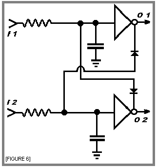
Figure 6 shows a Pair of Nu's linked together to produce another type of
First Come First Serve circuit. |
|
|
|
 |
|
|
|
 |
|
|
|
|
|
As with the Nv version the first Nu to fire functions as normal but the second neuron is forced to wait until the first one has completed it's cycle before it can begin it's own cycle. |
|
|
|
Combinations |
|
|
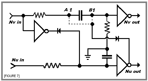
| Of course combinations can also be done. Such as in Figure 7. The following is only a quickly drawn example and not one that I have actually used for anything yet. It's just here to show that there are many possibilities here. |
|
|
|
 |
|
|
|
A Side Note |
|
|
|
Figure 8 though not linked neurons is a similar application. Basically it is the simplified circuit from figure 1, but with the addition of a pair of switches added They can be any kind of switch that works for your purpose.
The switches in this case are there to act as limits to the movement of a leg assembly. The same arrangement could be used with a head assembly to limit how far in either direction it can move thereby restricting its field of view. |
|
|
|
 |
|
|
|
 |
|
|
|
|
|
The components in gray are there to provide a signal to other parts of the robot that may need to respond to a limited condition. The diodes could be LEDs to provide a visual indication instead. |
|
|
|
8888888888888888888888888888888888888888888888888888888888888888888888888888888888888888
8888888888888888888888888888888888888888888888888888888888888888888888888888888888888888 |
|
|
|
An example |
|
|
|
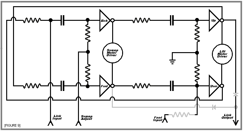
The following is just one example of what I think can be done with the concept of parallel linking. It uses the first come first serve arrangement.
The idea is a hexapod controlled by six linked micro-cores. One to operate the two motors in each leg. Each micro-core would be coupled to at least two others.
They would also incorporate an input to modify the downward stroke of the leg and another that will allow altering the length of the forward and backward sweep of the leg. These two inputs, I believe, will improve stability and provide a means of turning the robot. |
|
|
|
The schematic in figure 9 is one of the leg micro-cores and shows were the link input, link output, sweep adjust, and foot input would be tied in.Each Nv neuron is marked with the movement it would control. |
|
|
|
 |
|
|
|
The link input, when pulled low, will cause the leg to pause before it sweeps toward the back. It will hold this state until both the neighboring legs have completed their upward and maybe its forward stroke.
At this point the link input will no longer be pulled low and the controlled leg will begin its backward movement. |
|
|
| The link output will go low during the up stroke of the leg. I have also shown a pair of diodes and a connection to the forward neuron in gray. This is due to the possibility that it may be necessary to hold the pause on the affected legs or both of these segments of the cycle. But I believe holding it for only the up stroke will be sufficient to maintain stability. Time and experimentation will tell. |
|
|
|
The sweep adjust input can be grounded directly (tied to the negative side of the power supply) or biased to cause the robot to turn by making the sweep of the legs longer on one side and shorter on the other side.
The bias can be through a variable resistor of some type tied to the ground on one side and the sweep adjust input on the other side. I actually have something more elaborate in mind but that is for another article. |
|
|
|
Lastly the foot input is for the purpose of modifying the duration of the downward stroke of the leg. This input can be tied to ground through a foot switch, halting the downward stroke.
The resistor shown in gray is an option if the switch is used. It would allow the stroke to be shortened rather than halted.
The switch could be replaced with a pressure sensitive resistor of some type.
If mounted on the bottom of the foot it could shortening the stroke according
to the amount of pressure applied. |
|
|
|
 |
|
|
The Links |
|
|
|
|
|
|
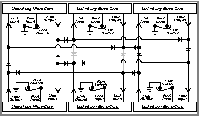
The six micro-cores are linked together by a network of diodes as shown in
figure 10. The sweep adjust input is not shown here because it is not important to the topic at hand. |
|
|
|
 |
|
|
| As you can see the link output of one micro-core is tied through two diodes to the link inputs of its two nearest neighbors. The result is that each micro-core interacts in such a way as to prevent, or at least minimize the chance of, adjacent legs being off the ground at the same time. The result should be a more level, and therefore more stable stride. |
|
|
| The two gray diodes in the center may not be used in this bot. I'm not sure that I need the center legs linked together.Again, time and experimentation will tell. But then, that's the fun of this hobby. |
|
|
|
Well that covers the basic concept and an example of the use of parallel linked neurons. I hope some of this will be of use to some of you, and that it inspires the creation of some interesting critters. |
|
|
|
So long, |
|
|
|
 |
|
|
|
|
Clifford Boerema Jr.
AKADroidmakr
February 6-2000 |
|
|
|
|
|
|
 |
|
 |
|
|
|


