 |
|
|
|
|
|
|
|
|
|
|
|
|
|
|
|
|
|
|
|
|
|
|
|
|
|
|
|
|
|
|
|
|
|
|
|
|
|
|
|
|
|
|
|
|
|
|
|
|
|
|
|
|
|
|
|
|
|
|
|
|
|
|
|
|
|
|
|
|
|
|
|
|
|
|
|
|
|
|
A Robot With Peripheral Vision |
|
|
| At the beginning of November of 2001 a very simple 74 HC 14 based head circuit was introduced to the BEAM community, by Martin Keen. As is so often the case, Wilf went on to present several improvements and variations on the theme I am of course referring to the: |
|
|
|
Schmitt Comparator Head |
|
|
|
(SC-Head or SC-H) |
|
|
|
If you would like to read the discussion on the original circuit, it begins at: |
|
|
|
http://groups.yahoo.com/group/beam/messages/18756 |
|
|
| I wanted to share an adaptation of the Schead v4, that I have been experimenting with. It is (for lack of a better term) a Master/Slave Schmitt Comparitor Head (M/S SC-H). With the addition of a 74 AC 240 or two (as motor drivers) and a pair of motors, you can put together an interesting little light seeking, wheeled robot with peripheral vision. |
|
|
|
 |
|
|
|
I would like to thank Dave for letting me post his version (the lower one) of the PV Roller schematic. I am sure that it will help make the function of the circuit more clear. |
|
|
Click on any image on this page to view |
|
|
|
|
|
|
|
|
|
|
I believe that the basic idea could be adapted to other types of light tracking robots and/or head circuits, such as Wilf?s PSH (power smart head). I have not tried this though, so I?m not sure how effective or useful it would be on circuits other than the SC-H based bots. |
|
|
|
Basically, what I did was to stack one SC-H on top of another. As shown in the schematic, the Master portion has four diodes (or two LEDs) between the photo-diodes. The outputs of the two inverters are tied to the positive and negative supply ends of the photo-bridge of the Slave section. They are also connected to four of the inputs (two each) of a 74 AC 240. |
|
|
|
The Slave section has only two diodes (or one LED) between the photo-diodes. This makes it respond to smaller differences in light levels than does the Master part of the circuit. The outputs of the inverters of the Slave SC-H, are tied to the remaining four inputs (again two each) of the 74 AC 240. |
|
|
|
The diodes between the photo-diodes create a constant voltage drop between the inputs of the inverters. They cause a dead band to exist between the thresholds of the two inverters. In a way they cause the circuit to act like a kind of window comparator. Without these diodes both inverters would always be in the same state. With them, there is a small range where their outputs are in opposite states. |
|
|
|
One side of each motor is connected (through the 74 AC 240) to one of the outputs of the Master SC-H. The other side of the motor is tied, (again through the 74 HC 240) to the output on the same side of the Slave SC-H. The photo-bridges of the Master and Slave sections are inverse of each other, (I.E. the positive and negative ends are at opposite sides). As a result, the output state of the inverters on the same side of each stage are also the reverse of each other, so the motor is turned on. The motors should be connected so that they will drive the robot forward when the light reaching the photo-diodes is in balance (equal on both sides). |
|
|
|
As long as the light reaching the photo-bridge of the Master SC-H is balanced, then the Slave SC-H acts as a regular, lone SC-H would. So, if one of the slave photo-diodes detects more light then the other, the inverter that controls the motor on that side changes states and is now the same as the inverter of the Master SC-H tied to the same motor. This turns that motor off and the robot will pivot around the stopped wheel toward the greater light source until the light on each sensors is balanced and the motor again begins to turn. |
|
|
|
Now if, one side of the Master SC-H detects more light then the other, the output of the appropriate inverter changes states. Now both outputs of the Master SC-H will be in the same state. This effectively disables the Slave photo-bridge. The Slave inverters now act as though their input were tied directly to the outputs of the Master SC-H. Thus outputs of the Slave SC-H be opposite of the Master SC-H. |
|
|
|
This results in the voltage that is applied to the motor connected to the side that has detecting the greater amount of light, being reversed. The motor will therefore turn in the opposite direction. This causes the robot to spin around the center point between it's two wheels toward the greater light source until the sensors are again in balance. |
|
|
|
Once More With Feeling |
|
|
|
The two remaining inverters were wired as a pair of Nu?s (one positive and one negative) and use to interface feelers to the circuit. The positive and negative inputs of the Master photo-bridge are connected to outputs of the Nu?s instead of to the positive and negative power leads as they would be in a regular SC-H. |
|
|
| If either feeler is tripped the output of the Nu inverter it is tied to changes state. This results in the Master Photo-bridge being disabled. The outputs of the master inverters are now in the same state, as would happen if it had detected more light on one side than the other. As described earlier this disables the Slave Photo-bridge and puts the slave inverters into the opposite state of the master inverter outputs. The bot will attempt to spin away from whatever it is touching. |
|
|
| Now, if both feelers make contact with something, then both Nu inverters change states. Again this disables the photo-bridge. The diodes between the Photo-diodes prevent the two Nu outputs from creating a dead short. The Master inverter outputs will be opposite the Nu inverter outputs and the Slave inverters outputs will be opposite the master. |
|
|
| The robot will back away form whatever it has made contact with. Making the time constant for the two Nu?s a little different, would cause the bot to spin to one side for an instant when the shorter period Nu times out. This would make it less likely to make contact at the same place and angle as before. |
|
|
|
 |
|
|
|
Truth Table for the PV (Peripheral Vision) Robot |
|
|
|
|
|
The idea for this adaptation grew out of an attempt to built a line follower that could track a � inch wide white line on a black background. I named the resulting creature: |
|
|
|
Cheesy Little Rat Bot |
|
|
|
I wanted to use a BEAM circuit. One that would not suffer from the problem created by differences in the ambient light. I have even seen a few microprocessor based line followers that have had problems with this. The SC-H seemed the best choice for a simple way to deal with this. |
|
|
|
Since it basically reacts to the difference between the amount of light the two photo-diodes are detecting, I hoped it would not suffer as much from the effects ambient light. I also wanted to have a second set of photo-diodes, just in case something went wrong and the first set lost the line. I originally was just going to "OR" the outputs of the two SC-H circuits together on each side. |
|
|
|
Then it hit me that the outputs of two inverters connected directly to the photo-bridge were of the opposite state. At least they are when the photo-diodes were receiving equal amounts of light. I have been experimenting with stacking sensor/behavior circuits on top each other and that may have also played a roll in sparking this idea. Anyway, I drew up a schematic of the photo-bridge of one SC-H fed by the output of another, and worked out how they would interact. It work out so well I decided it would be the perfect circuit for the line follower. |
|
|
|
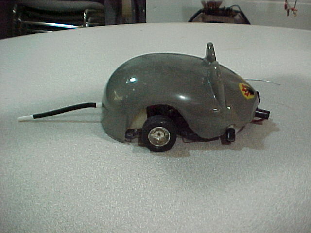
I built the circuit in the second schematic, and mounted it into a Wall Hugger kit that looked like a mouse. I had found this kit at a local hobby shop. A company named Tamiya manufactures it. In fact they produce several interesting kits and accessories that could be used for educational purposes or easily adapted for use in building robots. |
|
|
|
See: http://www.tamiya.com |
|
|
|
 |
|
|
|
 |
|
|
|
|
|
 |
|
|
|
 |
|
|
|
Click on any image to view |
|
|
|
The bad news is that the motors that came with most of the kits I have picked up were not very efficient. I had to use transistor H-bridges to provide the over 300ma of current needed for the ones that came with the kit. |
|
|
|
Holding the Line |
|
|
|
For line tracking, the four photo-diodes were mounted about � of an inch apart in a straight line across the base of the bot looking downward. Four LEDs were also mounted to illuminate the line. In this application both the Master and Slave had only two diodes between the photo diodes. The circuit worked well. |
|
|
|
Unfortunately the mechanics of the bot left a lot to be desired. It was sluggish, ran rough and drained batteries very quickly. I think I may have too build another one but this time use a custom made platform with much better motors. |
|
|
|
Putting A Stop To It |
|
|
|
Since Cheesy was to be a line follower, he did not need feelers. I did however, needed an easy way to turn his motors off and on. I did this by using the two extra inverters to build a simple flip-flop with Set (Start) and Reset (Stop) switches. |
|
|
|
 |
|
|
|
The Reset switch turns off the motors by toggling the flip-flop so that it pulls the Enable pins of the 74 HC 240 high, and thus putting the chip outputs into the tri-state or open state. |
|
|
|
This also makes it simple to make adjustments to the robot without having to deal with spinning motors or turn off the power to the entire circuit. |
|
|
|
When the adjustments are completed, the Start switch can be pressed, thus toggling the flip-flop back so that the Enable pins are now pulled low. The outputs of the 74 HC 240 are then active and the motors are turned back on. The feeler switch that was originally used to let the bot follow (hug) a wall became an easy to trigger Start switch. I mounted another switch to act as the stop switch. |
|
|
|
If you would like to see Cheesy in (snicker) action, you can watch a video clip of him competing (huge belly laugh) at the Chibots Line Follower contest held on Feb. 10 - 2002 by going to: |
|
|
|
http://www.wrightbrothers.net/eddy/video/ |
|
|
|
And Clicking on: ratbot.wmv |
|
|
|
You can also see the results of the competition are posted on the club website at: |
|
|
|
 |
|
|
|
www.chibots.org |
|
|
|
I Have Seen The Light |
|
|
|
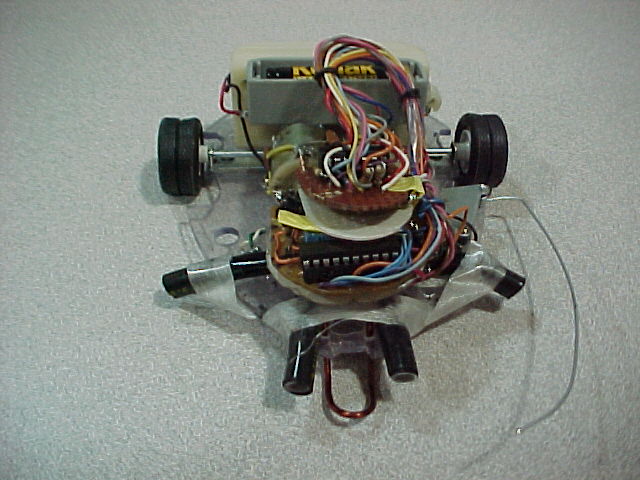
On the other hand as a light seeker, Cheesy works very well. I?ve had fun making him chase a spot of light from a flashlight around on the floor. He has even been able to detect and react to the flashlight spot on the floor of the brightly lighted lab where I work. |
|
|
|
For this purpose, the photo-diodes were mounted at four different angles across the front of the robot. Also remember, that as a light seeker, the Master SC-H has four diodes between the photo-diodes. |
|
|
|
The next Generation |
|
|
|
I have started working on another robot that uses the M/S SC-H arrangement. The base and motors are a toy RC car (with the body removed) that I picked up at a rummage sale for a buck. I am presently calling this one: |
|
|
|
SCar |
|
|
|
Since unlike Cheesy, it has a separate steering motor and only one drive motor, I?m using a 74 HC 139 to direct the outputs of the M/S SC-H circuit to the appropriate motor(s). |
|
|
|
I am also using SCar to continue experimenting with Stacking separate Sensor/Behavior circuits onto a robot. I will post more as progress is made. |
|
|
|
 |
|
|
So long, |
|
|
|
|
|
Droidmakr |
|
|
|
|