PARKVILLE PIKE PROJECT: BENCHWORK
Due to my limited experience/talents as a carpenter, I chose to build L-girder benchwork instead of using butt-joint construction. L-girder benchwork is stronger and more flexible while not requiring as precise cutting and fitting. My construction "bible" was How to Build Model Railroad Benchwork, 2nd ed. by Linn H. Westcott (Kalmbach Publishing, 1996). For ease of discussion, I will address the construction of the basic benchwork, the construction of the risers and subroadbed, the laying of roadbed and track, and construction of control panels in separate sections.
General Design Considerations
- The benchwork must fit the room in which it is placed. As discussed in the layout design section, space available and physical characteristics of that space drove the design.
- Make benchwork wider at turn back curves, return loops, etc. Make it narrower where additional aisle space would help -- around control panels, yards, and places where people gather.
- Plan aisles for best walking, viewing, and operating; fit the trackplan into the remaining space.
- Aisles should be at least 24 inches wide.
- Allow an additional 12 inches around control panels or yards.
- Layout height and width:
- Limit maximum reach over scenery to 30 inches.
- Allow 38 inches below benchwork girders.
- Track should be about 50 inches above the floor (eye level when seated on 20 inch chair).
- Track looks more realistic if it doesn't run parallel to table's edge. If the track can't curve, angle or curve the benchwork.
- For L-girder benchwork:
- For 1x4 in girders:
- Maximum overhang is 52 inches.
- Maximum spread between legs is 13 feet.
- For 1x4 in joists:
- Maximum overhang is 30 inches.
- Maximum spread between girders is 90 inches.
Plan View
I designed the benchwork (as well as the overall track plan) using Cadrail software from Sandia Software. In addition to producing a clean diagram for use as a benchwork blueprint, Cadrail will produce a detailed material listing of all elements in the benchwork layer. From this it is straightforward to make a tailored list of each type of material (1 x 4s, 1 x 2s, etc.), how many, of what length. The basic benchwork consists of two benches: the Boreas Bench and the Parkville Bench. The gap between benches (access to undereave storage) will be spanned by four removable "bridges". For any subsequent discussion of dimension or position, the back left (top left on diagram, along main wall) corner of each bench will be x (left to right dimension) equal zero and y (front to rear dimension) equal zero. Thus all x dimensions are positive. On Boreas Bench, all y dimensions are negative. On Parkville Bench, y's are both positive and negative because part of the bench extends back into the alcove.
Complicating this benchwork is the fact that the front left-hand corner (2 foot by 3 foot) of the Boreas Bench is lowered 15 inches. That means that the front leg of the keeper joist at x = 3.5 feet must support two L-girders, and the short front leg at x = 0.5 feet is not part of a keeper joist.
General Benchwork Planning Considerations
Materials
- Wood (Grade 2 pine):
- 2 x 2 inch: Used for legs.
- 1 x 4 inch: Used for girder web and joists. I would have preferred 1 x 3s, but my local building supply store did not carry that size.
- 1 x 2 inch: Used for girder flanges and leg braces.
- Plywood: 1/4 inch used for gussets for leg braces.
- Hardboard (Masonite): 1/8 inch used for backdrop.
Fasteners/Adhesives
- No 8 1 1/4 inch wood screws.
- Elmer's Carpenter's glue (for the girder web - flange joint).
Step-by-Step Construction of the L-Girder Benchwork
I initially built L-girder benchwork for a layout in my Frisco townhouse. After I moved to my present house, I built the benchwork reusing as much of the previous benchwork as possible. Those steps done for the Frisco townhouse and not repeated are so annotated.
- Cut the parts (done for Frisco layout).
- Cut parts for girders, legs, braces, joists, and gussets.
- Girders and joists were cut per the benchwork plan diagram.
- I cut all joists at this time. Westcott recommends cutting only keeper joists now, but I cut all wood to be able to get it all indoors and up in the loft.
- The legs should be cut long enough to reach the top of the keeper joists. For my layout, this meant 45 inches, which would be the lowest level of the bottom of subroadbed. I cut 10 legs.
- Long braces were cut at 5 feet, which should put them at about a 45 degree angle. I cut 10 of them.
- Cross braces were cut between 3.75 and 4.25 feet, working out dimensions from a right triangle formed by the keeper joists and legs. I cut 10 of them.
- Assembled the L-Girders (done for Frisco layout).

- Selected the straightest pieces of wood for the girders.
- I needed one 10 foot, three 9.5 foot, one 6.5 foot, one 5 foot, and one 3 foot girders. The 1 x 2 inch girder flanges came in 8 foot lengths, so the flanges of the longer girders had to be made of two pieces of wood.
- The flange of the girders which butt up against the rear 10 foot girder were made 1 inch short of the end of the web to allow overlap of the flange of the rear girder.
- Drilled pilot holes and inserted screws through flange into web at about 1 foot intervals.
- Removed screws and spread a bead of carpenter's glue along length of web. Reinserted and tightened screws.
- Wiped away any excess glue oozing out of the joint.
- After allowing the glue to set overnight, removed the screws from the girders.
- Inventoried lumber remaining from Frisco layout for reuse and cut/spliced L-girders and joists as required.
-
L-GIRDERS
| HAVE ON HAND |
NEED |
| 10 ft |
2 x 12 ft |
| 3 x 9.5 ft |
10 ft |
| 6.5 ft |
7 ft |
| 4.5 ft |
3 x 3.5 ft |
| 3 ft |
2 ft |
The following actions converted L-girders from what is on hand to what is required:
- Cut one 9.5 ft girder to 7 ft; used excess to extend one 9.5 ft girder to 12 ft. Spliced using 8 in 1x4 block on the rear of the girder web attached with 6 screws.
- Cut 6.5 ft girder to 3.5 ft; used part of the excess to extend (splice) one 9.5 ft girder to 12 ft.
- Cut 4.5 ft girder to 3.5 ft.
- Cut 3 ft girder to 2 ft.
- Combined (spliced) pieces to build 3.5 ft.
-
JOISTS
| HAVE ON HAND |
NEED |
| 2 x 8 ft |
6 x 5 ft |
| 5 ft |
4 x 4.5 ft |
| 10 x 4 ft |
4 x 3 ft |
| 4 x 3 ft |
2 x 4 ft |
| 3 x 2.5 ft |
3 x 2.5 ft and 1 x 2 ft |
The only critical joists are those needed for keeper joists: 3 x 5 ft, 2 x 3 ft, and a 2.5 ft attached to a single leg. These were cut from stock on hand. Other joists were spliced (as above) as required.
-
LEGS and BRACES
Five keeper joist/leg sub-assemblies remained from the Frisco layout. There is also more than enough of this (2 x 2 in and 1 x 2 in) stock on hand.
- Assembled the five leg, cross-brace, keeper joist sub-assemblies.

- Disassembled the sub-assemblies remaining from the Frisco layout.
- Keeper joists are those attached to the leg pairs during the construction phase. Marked on the five keeper joists where each leg should be attached (see plan view of benchwork).
- Attached each 45 inch leg to the keeper joist with one screw.
- Added cross brace from 5 inches under joist on one leg (to allow L-girder to be attached to front of leg - Lesson Learned from Frisco layout) to 3 inches from bottom of other leg. Used a carpenter's square to ensure legs are perpendicular to joist. Attached brace with one screw on each end.
- Turned sub-assembly over and attached the other brace in the same manner as above.
- Added second screw to each joint.
- Trimmed ends of cross braces to ensure they wouldn't interfere with subsequent steps.
- Attached short (30 inch) leg to proper position on 2.5 foot joist. Ensured leg was perpendicular. Braces will be added later.
- Trimmed 2 inches from the bottom of all 11 legs. This was done to lower track elevation (from floor) due to error in planning.
- Assembled the L-Girder Benchwork.

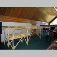
- Built the Parkville Bench first as it was the more straightforward.
- Clamped a leg sub-assembly to correct distance from each end of each L-girder. Note that the L-girder goes in the front of the legs so that the flange is forward.
- Ensured flange of the each girder was snug against the bottom of the keeper joists. Used a single screw to attach the girder web into each leg sub-assembly. Removed clamps.
- Clamped a girder brace with triangular gusset already attached to a leg so that one end (with gusset) was just above the floor and brace extended up at about a 45 degree angle. Clamped top of brace to inside of girder web. Trimmed off any excess
- Screwed gusset into leg with two screws and removed clamps.
- Used level to ensure leg sub-assembly was vertical, and screwed brace to girder web with two screws.
- Attached brace to other leg sub-assembly in the same manner.
- Attached the braces to the other L-girder in the same manner.
- Built the Boreas Bench in a similar manner.
- Attached the rear 12 foot L-girder to the end keep joist/leg sub-assemblies. Attached braces to rear L-girder.
- Attached the front 7 foot L-girder to the right end and center (front leg) sub-assemblies. Attached braces to front L-girder. Screwed back end of the center keeper joist to the flange of the rear L-girder (with a screw up from the bottom of the flange) at the proper position (x = 3.5 ft).
- Attached the two 3.5 foot L-girders to left and center (back leg) sub-assemblies. The lower L-girder top is at 24.5 inches. Attached braces to lower L-girder.
- Attached the short leg to the front left of the bench. Screwed back end of joist to front leg of the left end sub-assembly. Attached low (24.5 in high) L-girder from the short leg to the center (front leg) sub-assembly. Attached brace from short leg to L-girder and cross brace from short leg to left end (front leg) sub-assembly.
- Placed, but did not attach, the remaining joists in their approximate positions. They will be screwed to the L-girder flanges after ensuring compatiblility with the track plan.
- Preparation for Backdrop.
- The backdrop should be attached and painted prior to additional work on subroadbed or track laying. Basic reason is that elevated roadbed will block the lower backdrop, especially near Boreas Pass.
- Knowing the size of the pieces of masonite which will be used for the backdrop, positioned joists to be under where the joints will be. Checked these positions against the trackplan to ensure against interference with turnouts. Joists ended up in the following positions.
- Boreas Bench:
- Keeper joist at x = 5.5 inches (left edge). This was already in position.
- Joist at x = 95.5 inches. This was new (added to benchwork) 60 inch joist.
- Parkville Bench:
- Joist at x = 0 inches.
- Joist at x = 47.5 inches. This was new 36 inch joist.
- Keeper joist at x = 125.5 inches. This was already in position.
- Attached these joists with screws through the L-girder flanges from below.
Top