Medium Mark III

Introduction
I have long been fascinated by tanks of the inter-war period. I think this stems from my very first visit to Bovington in 1969 when I was most impressed by the A1E1 Independent. Since that time, I have made very many models and still possess some of my early schoolboy attempts at kit building and conversion. I have generally stuck to modelling in 1/76 or 1/72 scales, initially because of cost constraints, and latterly due to space considerations.
I am not quite sure what started me on the road to making the Medium Mark III, but it proved to be a long road indeed. Firstly, I could find no scale drawings and secondly to draw my own meant collecting all the photographs and references I could find. I was greatly helped in this by Chris Evans of Chris Evans Books, David Fletcher of the Tank Museum and by the staff of the Imperial War Museum Picture Archive. Even so, there are still aspects of the drawings that are not certain in their detail, but unless more pictures come my way I believe the drawings to be as accurate as is currently possible. In all, this project has taken about 4 years of somewhat intermittent work.
The following account is in three parts: Firstly, the vehicle itself, secondly how to construct a 1/76 scale model from brass sheet using photo-etch techniques and finally how this applies to the Medium Mark III..

History
In 1926 the War Office wanted to replace the existing Medium Mark II Tanks with an improved vehicle. Improvements were proposed in lubrication, deployment of machine guns, accessibility, armour and crew safety and comfort, fording capability and all-round vision. A weight limit of approximately 16 tons was given and these vehicles were therefore known as “16-tonners”. From these requirements, Vickers produced the A6 which ran to three mild steel prototypes, the chief failings of which were found to be in the suspension and gunnery arrangements. They continued in use as experimental test beds until 1938 and were the first vehicles to use the new Wilson epicyclic gearbox that was the predecessor of the famous Merrit-Brown gearbox, first used in the Churchill tanks and subsequently in Chieftain.
As a result of the perceived shortcomings of the A6 designs, emphasis shifted to work on the Medium Mark III, started in 1930 following a request from the War Office to Vickers. This new vehicle was similar to the A6 series, but had a completely redesigned turret and used Cemented Tank Armour, an improved variety of armour plate. Unfortunately, the suspension was not improved and still suffered from “bottoming” over rough terrain. A total of three Medium Mark IIIs were built, one by Vickers and two by the Royal Ordnance Factory (ROF), Woolwich. The Treasury considered these vehicles to be too expensive at around £16,000 apiece and no further orders were placed.
Table 1. Mark III Specification
|
Weight (tons) |
Length |
Width |
Height |
Engine |
Max speed (mph) |
Radius (miles) |
Armament
|
Armour (mm max/min) |
Crew |
|
|
Main |
MGs |
|||||||||
|
16 |
21’6” |
8’9” |
9’2” |
180 hp Armstrong Siddeley 1800 rpm, air cooled V8 |
30 |
120 |
3 pdr |
3 x Vickers 0.303 |
9 / 14 |
7 |
Table 2. Individual Vehicles
|
Designation |
W.D. No. |
Registration No. |
Maker and Year |
Comments |
|
Mark III E1 |
T870 |
MT9707 |
ROF May 1929 |
|
|
Mark III E2 |
T871 |
MT9708 |
ROF May 1929 |
Destroyed by fire |
|
Mark III E3 |
T907 |
MT9709 |
Vickers Armstrong Feb 1931 |
|
Markings

Markings for T870 (MT9707) are shown as used on exercises. The RAC pennants were placed on the sides of the turret bustle, pointing to the rear. The MT9707 number plates were placed as shown in my drawings. The T870 markings were placed towards the rear of the sides of the mudguard stowage bins.
T907 (MT9709) is seen in photographs with a different style registration plate, RAC pennants as above and with either plain stowage bins or with a large white 907 on the front sides of the stowage bins. There is a picture of this latter configuration in Mechanised Force by David Fletcher. I have no clear details of the markings for T871 (MT9708). This vehicle was destroyed by fire and was subsequently used in tank recovery trials.

The Drawings
Previously, 1/32 scale drawings have been published in Military Modelling (Feb 1986). Although basically correct, there are some inaccuracies, particularly in respect of the engine deck layout. Some of the issues are still not fully resolved in my drawings. The Tank Museum Library has plan and side elevation sectional drawings. These were invaluable for determining many details of the suspension, driver’s position and general layout. They also provided essential clues to the rationale behind placement of many of the rear deck features. Unfortunately, none of the pictures I found showed the top of the engine deck beneath the turret bustle adequately. Three particular problems on the engine deck present themselves. The first is the position and form of the hatch at the right hand top end of the deck. A clue to the answer here is that the sectional drawings show two different sized handles and that there is clearly a filler cap in this region that the hatch fits around, thus explaining the two different handles. The exact shape of the recess for the filler cap in the hatch is, however, speculative. Secondly, the exact nature of the edge of the grilled panels under the raised cover is not certain, especially in respect of the rear edge where the exhaust pipes enter the vehicle. A rear elevation photograph provides some information but is difficult to interpret. The sectional drawing does show the louvers quite clearly and it is likely from the photograph that these are longitudinally divided into panels. Thirdly and finally, there is a grill on the left hand side top of the engine deck. How far it extends towards the centre line is uncertain. I believe it either extends as far as the vehicles’ centre, or as far as the centre of the raised cover below the grill.
Most of the other features are fairly clear from the available photographs.
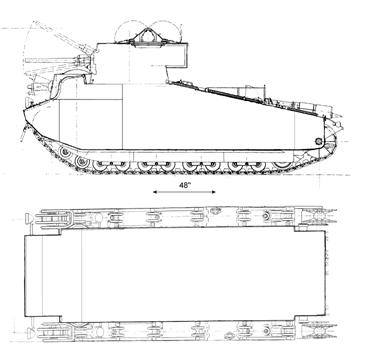
Click on drawing for higher resolution .pdf
Sectional Drawing
(redrawn to exclude internal details)