48 kHz Infrareds Emitter and Receiver, Rangefinder
By Dillian Wong, 24/3/04
ABSTRACT
Infrared
is commonly used both in communication, control and object detection. Objects
that generate heat also generate infrared radiation. Many sources of infrared
radiation generate and around the environment. The sun, standard light bulbs,
computer monitor, visible light LEDs and even animals and human body produce
different level of infrared light. If a device simply relied on the presence or
lack of presence of infrared light, the communication or object detection
algorithm would receive false and noisy readings. The common way of making the
Infrared signal more noticeable is using the modulation technique. That is the
information of Infrared signals does not only depend on the signal magnitude,
but depend on the variation of the signal.
The noisy infrared radiation can be rejected, as the particular frequency of
modulation technique is selected by the application.
INTRODUCTION
Infrared LEDs are commonly used for object detection in robots. Blinking the LED on and off can improves long-range detection and reduces false triggers. In this project, I implement a 48kHz modulation frequency. Because the application of this project is measure the distance of the targeted object, no communication is required. Thus, only carrier is enough, the reflected back signal magnitude in this case is represented the distance of the targeted object. For the further stage sof the AD conversation, it is necessary to converse the sinusoidal signal back into state DC voltage. Otherwise, the AD converter output will be fluctuate seriously. And it is not easy to get the means values.
CIRCUIT DESCRIPTION
The following will explain the usage of the electronic components, and how they work to make a infrared RangFinder. This project mainly divide into 4 part; one is the oscillation circuit for the Infrared modulation, following is the emitter circuit, receiver circuit and the last is the envelop detector circuit. After the 4 stages the output DC voltage is expected. This DC voltage represent the distance of the measured target object distance.
Oscillator
|
|
|
555 as a astable
multivibrator
The capacitor voltage then decreases until it drops below the trigger level Vcc/3. The flip-flop is triggered so that the output goes back high and the discharge transistor is turned off, so that the capacitor can again charge through resistor R1 and R3 toward Vcc.
|
|
Th
= 0.7(R1+R2)C2 f= 1/T = 1/(Th +
Tl ) = 1.44/(R1+2R2)C2
|
Infrared Emitter
|
|
The
555 Circuit are used to generate a square wave at a desired frequency. The
square pulse is fed into the transistor 2N2222 through a base resistor.
The transistor acts as an on/off switch for the infrared LED. Because the
emissions are infrared and very fast, neither is visible to human eye. Although the Infrareds Emitter is modulated with 48kHz carrier, if used for object detection, the signal need to travel the distance to the object and then reflect back the signal to the receiver, the distance becomes importance factor. In this project, infrared circuit development, I find the valid distance is about 3cm to 14cm. Digital still cameras or video cameras can be very helpful in testing and debugging an infrared circuit. Although the naked eye cannot see that an infrared LED is turn on, CCD camera can! The below image show a lit infrared LED. Infrared LED appears as faint pink or purple to a CCD camera
|

At
the receiver side, the received signal a 48kHz sine wave. If the application of
infrared is only used to turn on something when the object is within a certain
distance, for simplicity, It can directly fed the carrier signal to a relay,
when the magnitude of the signal is large enough, the relay will turn on. The
reason is the signal is fast change enough that causes the relay do not have
time to turn off. Therefore, overall the relay is always on when the magnitude
large enough.
If
the application require an analogy voltage to represent the distance, that means
we measure the intensity of the reflected infrared signal, when the detected
object is nearby the measured intensity is greater, and when the object is far
the intensity is smaller, in this application an envelope circuit is a must.
Without envelope circuit, the forward stage of the AD converter can be measure
the DC voltage, or the output of the AD converter is fluctuating, the
fluctuating level depend on the speed of AD conversion time and the carrier
frequency.
Because
infrared receivers amplify the signal to improve detection, electrical noise
generated from the oscillator can leak into the receiver and trigger a false
detection. Meanwhile, 9041 (after the stage of receiver transmitter) may be
perfectly work in linear region. The following is the measurement of the
receiver waveform. Electrical noise isn't a problem for VCRs or most consumer
devices as they tend to contain either a transmitter (remote control) or a
receiver (CD player), but not both. Use of decoupling capacitors and metal
shielding helps to lower the noise.(
The
Envelope Detector
The simplest form of an envelope detector is a nonlinear charging circuit with a fast charge time and slow discharge time. It can easily be constructed using a diode in series with a capacitor. A resistor placed across the capacitor controls the discharge time constant.
The input signal waveform charges capacitor C to the waveform's maximum value during positive half-cycles of the input signal. As the input signal falls below its maximum, the diode turns off. This is followed by a slow discharge of the capacitor through the resistor until the next positive half-cycle. when the input signal becomes greater than the capacitor voltage the diode turns on again.
If this time constant is too large, the envelope detector may miss some positive half-cycle of the carrier and thus will not reproduce the envelope faithfully. If the time constant is much too small, the envelope detector generates a very ragged waveform, losing some of its efficiency. The resultant detected signal is usually passed through a low-pass filter to eliminate the unwanted harmonic content.
The
calculation of envelop circuit component values is RC>= T. I used R=750k and
C=10n. ie RC=7.5ms > 1/48k = 0.02ms. I take large time constant is because I do not want the ragged DC output. Also in my application, rang finder, the state
DC voltage is important for the AD conversion.
MEASUREMENT RESULT
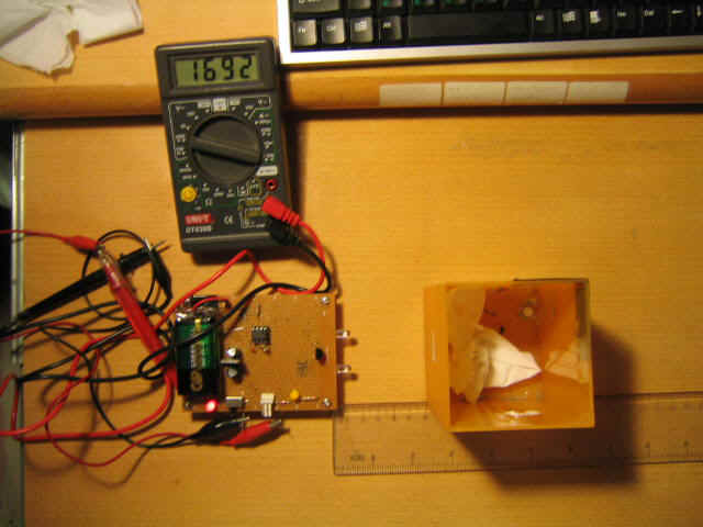
The following is the photo on the left side indicated how I measure the Rangefinder. I place a obstacle in front of the Rangefinder then measure the DC output Voltage. In the diagram, we found the voltage is varied form 1.5V to 2.5V, to represent the distance from 12cm to 2cm. The range is more suitable for more application, when the object near by or a object in front of the sensor. Then devices will turn on something. The required distance can use a comparator, compare the DC voltage output with a desired reference voltage.
|
|
|
|
Distance /cm |
2cm |
3cm |
4cm |
5cm |
6cm |
7 cm |
|
Voltage /V |
2.58V |
2.16V |
1.923V |
1.774V |
1.689V |
1.629V |
|
8cm |
9cm |
10cm |
11cm |
12cm |
13cm |
14cm |
|
1.592V |
1.567V |
1.551V |
1.523V |
1.512V |
1.505 V |
1.498V |
|
15cm |
16cm |
17cm |
18cm |
19cm |
20cm |
21cm |
|
1.493V |
1.490V |
1.487V |
1.484V |
1.482V |
1.480V |
1.478V |
PROBLEM
ENCOUNTER
CONCLUSION
I
develop the circuit is for the range detection of the robot Hex-avoider
competition. It
is a six-legged robot. With a developed control program and some sensor,
it can move independently and avoid obstacles.
When the obstacles is
EXTEND