Hacking the 'Commodore 64' DTV - PAL version

Hmm... The wife is away for the weekend... what to do? Spend the weekend to convert a $25 toy into a home-built Commodore 64.
Obviously.

DTV ImageFor 
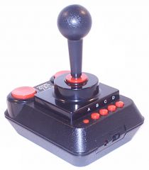
those who don't know, the DTV is a simple 25-dollar TV videogame that appeared in 2004. Built into a battery-powered joystick is actually a very complete Commodore 64 clone with some 30 videogames. It has an interesting pedigree, designed by Jeri Ellsworth  after she came up with the Commodore One.
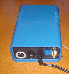
The designers have clearly aimed to make the toy hackable. In fact, it contains something like a '2005 motherboard' for a stand-alone C-64 clone. Hook up a PC keyboard, a 1541 disk drive, add external joystick connectors and, and, er, well, you have a new C-64. How useful is that?!

The initial version was a NTSC design. A European PAL version finally appeared in November 2005. It adds some improvements for those hacking around: it supports both joystick ports; and it has a flash rom containing the 2MB 'virtual hard disk', creating the hope that this flash is rewritable. Writing this in November 2005 though, I haven't heard anyone actually having done that.
DTV with 1541 and keyboard
One thing seems to bother lots of people: the PAL version apparently shows colours that deviate from the original C-64. Maybe, but nothing that I notice particularly. Using a TV as a monitor never was a great idea, and my DTV does exactly as badly as my original C64 when it comes to the TV picture...


My DTV Hack

Here is my version of a full C-64 replica built from the PAL version of the DTV, and a description of how I built it. How good is this little blue box as a C-64 clone? Not perfect. But still, it's a fun project and it does run most  software - how much I don't know, because I haven't tested it fully yet. The problems I know of so far:
Who cares? It's still a near-perfect replica of the C-64, and it is a simple/cheap/fun hack.


Requirements
To make the DTV into a fully connected C64, you only have to hook up connectors to some solder points on the board. People either put the connectors into the original DTV case, or they take out the board and put it into a new case with more space.
I chose the second option, a proper new case. They sell a perfect one at www.conrad.ch (or .de, presumably), just large enough to fit the board and still leave a bit of room to wire up the connectors. The front and back are plastic, making it easy to cut out space for the connectors. Also, you can easily mount the board inside, the screws fit. Order number 52 31 17-99 for 6.75 euros...

BackFrontLEFT: The back panel holds the keyboard/disk drive/joystick connectors. I used the original unit's video cable without modification. Its pull-protection thingy ( Thingy ) locks neatly into a cut-out slot in the back panel.

As you can see, I still have to add the second joystick port and also a decent power connector...

RIGHT: The front panel is equally simple: just a reset button and the power switch taken from the original DTV. It neatly drops out of the DTV case, and gives you a built-in power LED and on-off switch that you can easily mount in the front panel with two screws.

Parts list:
  • a push button for resetting the DTV;
  • a 6-pin DIN connector (female) for the disk drive connector;
  • a PS/2 mini-DIN connector (female) for the keyboard;
  • two DB-9 connectors (male, ususally for RS-232) for the joystick ports;
  • a simple plastic case that turned out to be the perfect fit.   
  • I forgot to buy a power supply connector. Hmm. Next time.

  • The mechanical work

    The pictures below show the construction process. All in all, it took only four hours!

    Opening the DTV shows the 'motherboard' (A), the board that I removed holding the fire buttons (B), and the power switch unit (C), that I kept. The second picture shows the board itself, before I removed the fire button board which is still visible on the right.

    Step1  step2

    Here's how the board fits into the case, and how the back panel was planned with the connectors. Not visible here is how I cut a small vertical slot into that back panel, that holds the video cable neatly in place. Good way to save on adding one more connector, whilst keepings things solid.

    Step3  Step4

    The finished thing, ready to be closed up. All I did was to add the connectors to the board. I soldered everything on the back side of the board, but that's a matter of preference I guess. Only things that remain to be done now is to add the second joystick connector and a proper power connector. For the moment, I still use the original case of the DTV as a battery holder.

      Step 6

     
    Soldering work:

    The PAL version of the DTV is different from the NTSC edition. Below are the links I used to get all the correct information for the PAL version.

    1 - Finding the soldering points for the keyboard and disk drive ports:
    Best shown in this Petscii forum thread. I made a copy of the most important picture, in case the link ever disappears. Zoom the picture to get the full details:

    Keyboard/Disk drive solder points
    Source: http://jledger.proboards19.com/index.cgi?board=dtvhacking&action=display&thread=1128627064

    Next to the three lines shown in the picture, the IEC disk drive connector also needs a GND wire. And the keyboard connector needs an additional GND and +5V. These additional wires that can best be soldered on to where the power leads come on the the board. I wrongly assumed that GND could also be found on the back of the board, just anywhere on the matrix. Not so - it's not GND but +3.3V! If you don't get things to work, check whether your GND wires really go to GND on the front side of the board. And whether your +5V is really +5V, not 3.3V.

    2 - Soldering points for the two joysticks:
    Best shown in this Petscii forum thread. I made a copy of the most important picture, in case the link ever disappears. Zoom the picture to get the full details:

    Joystick solder points
    Source: http://jledger.proboards19.com/index.cgi?board=dtvhacking&action=display&thread=1131108146

    Joystick #2 is actually the one that is used by all the games that came with the DTV. There are six wires to hook up to the DB-9 connector:
    Joystick #1 is less used on the C64. Still, it is useful to have the connector available:

    3 - Connector pinouts:
    To know how to hook up the connectors to the wires, look at this site or this one. It's quite simple, as summarised below. Note that all connectors are shown from the front side, looking from the outside in. Meaning you should make a mirror-image if you want to look at the solder side!
    Keyboard Connector
    (viewed from the front)

    PS2 connector pinout
    Disk Drive Connector
    (viewed from the front)
    Disk Drive connector pinout
    Joystick Connectors
    (viewed from the front)
    Joystick connector pinout
    1- DATA 2- GND 1- UP
    3- GND 3- ATN 2- DOWN
    4- +5V 4- CLK 3- LEFT
    5- CLK 5- DATA 4- RIGHT
    6- FIRE
    8- GND
    Sources: http://www.x-orion.de/dtv/wuppertal/1/8.html and http://t5000.blogspot.com/


    Thanks to the people who did all the figuring out!

    --------------------------