The
unofficial K7S5A motherboard guide
This is a copy of the guide aviable at the EZboard
K7S5A Forum. You can find the surce here.
The unofficial K7S5A motherboard guide (version 1.2)
By Oken, AlphaArms, daveg4otu and Milt.
Contents:
Scope of this guide
1. Building a system
Board versions/revisions
CPU support
Harddisk support
Memory types
FP1 connections
USB connections
PCI sharing layout
Power supply specifications
Operating System installation
2. Installing software/drivers
Latest SiS AGP port driver
Onboard sound driver
IDE driver
Temperature/voltage monitor
3. BIOS
BIOS setup pictures (screendumps)
How to reset the CMOS
Choosing the right BIOS
Bios settings
Flashing the BIOS
How to modify the default settings in a BIOS .rom file
4. Troubleshooting
RMA or not?
Distorted sound when using a PCI graphic card
Secondary IDE drives are not detected at bootup
System will not POST
System randomly unstable. System works only at fsb/mem 100/100. System
crashes after some time running full load
Bios (cmos) settings lost on startup
Blank screen after POST
Keyboard not working during POST
Bios error codes (beeps)
SSE disabled when using Thoroughbreds
ACPI in Windows 2000/XP *
5. Overclocking
DDR bus speeds explained *
Relationships between FSB, PCI and AGP *
FSB overclockning (with honey X OC bioses) *
FSB overclockning (with software)
Tuning memory timings
Changing multiplier
Changing Vcore
(
* = Not written yet
)
Scope of this guide
This guide deals mainly with the "classic" K7S5A board, i.e.
version 1.x and 3.x. The K7S5A Pro v. 5 uses a different PCB, has an
extra onboard VIA USB controller and finally uses different bioses.
But despite of the differences, many things relating to the non-pro
board are also true for the Pro board.
1. Building a system
Board versions/revisions
There are basically three main versions of the board, v1.x, v3.x and
v5.0. Add to that a number of revision numbers. I am not going to go
into details about the revisions, because frankly, it doesn't matter
much today.
The only difference to care about between the v1.x and v3.x boards is
the chip used for onboard sound. More on this later.
CPU support
If flashed with the right bios version, all board versions support
Duron Spitfires, Duron Morgans, Athlon Thunderbirds*, Athlon XP
Palominos and Athlon XP Thoroughbred A/Bs based on a 100 (200DDR) or
133 (266DDR) FSB. The board also unofficially supports the Athlon XP
Barton, but you will not be able to boot the board at the Barton's
nominal 166 or 200 MHz FSB because of a hardware limitation, therefore
you will have to either underclock your Barton or experiment with
software FSB changing to run it at 166MHz FSB.
In other words, you can put up to an Athlon XP 2400+ or an Athlon XP
2600+ (only the 266FSB version) on the K7S5A.
*Some boards can have problems with the Athlon Thunderbird ~1400 model,
more info
here
.
Note that the bios' default FSB setting is 100MHz (200DDR), so a CPU
with a 133MHz (266DDR) FSB will run underclocked until you manually
set the FSB/MEM option to 133/133 in the CPU PnP setup page in the
bios.
The 266FSB Athlon XP processors come in two main flavors, one type
build with a 0.18µ manufacturing process (AKA Palomino) and one type
build with a 0.13µ manufacturing process (AKA Thoroughbred
"A" and "B"). The 0.13's smaller transistors
generate less heat and run with a lower voltage, which makes is a
cooler-running and more overclockable CPU compared to its 0.18
brothers running the same frequency.
To find out if your chip is a Palomino or a Thoroughbred model, you
can download
WCPUID
and look at the Family-Model-Stepping ID (standard)
If you get 6-6-x, you have a Palomino. If you get 6-8-0, you have a
Thoroughbred A. If you get 6-8-1, you have a Thoroughbred B.
You can also just look at the core shapes.
This
is what a Palomino looks like.
This
is what a Thoroughbred looks like (both models can be either brown or
green).
If you use a Thoroughbred core CPU on the v1.x and 3.x boards, SSE*
will be disabled at bootup because of a bug in the official v1.x/v3.x
bios versions. You can fix this by flashing an unofficial modified
bios based on the Pro version. More info in the bios section of this
guide. The Pro board bioses does not have this bug.
*(Streaming SIMD Extensions, an extra instruction set build into newer
CPUs. Certain programs, mostly audio/video encoders, 3D renderers and
mathematical/scientific programs, can be optimized to use SSE, and
will thus run faster if the CPU is SSE capable)
Harddisk support
The board supports IDE ATA33/66/100 drives up to 130GB. ATA133 capable
drives can also be used, but will "only" run ATA100 speed.
Memory types
The board officially supports two PC100/133 SDRAM modules or two
PC1600/2100 DDR SDRAM modules. You should generally use memory sticks
with a named brand and stay away from ultra-cheap noname modules.
Some boards seem to have stability problems using two PC133 sticks at
the same time, so if you experience stability problems, use only one
stick of PC133 or use DDR memory while troubleshooting. Boards with
2xPC133 issues normally have no problems running 2xDDR.
If you are buying new DDR memory, consider getting PC2700 or PC3200
memory instead of PC2100. The faster memory will work on the K7S5A (at
for example PC2100 speed), and it work in your next computer too.
Newer CPUs and boards will need memory capable of running at least
166MHz (the speed of PC2700). Going PC2700 or PC3200 is also a good
idea if you consider overclocking the board. More on this later.
For a performance comparison of PC133 SDRAM and DDR memory, look
here
.
FP1 connections
The connectors for the power on switch, power LED, IDE LED, speaker
and reset button should be hooked up like this:
To fit a three-pin Power-LED connector on the two pins on the board,
you must either cut the connector in half vertically and rotate the
two pieces 90 degrees, or move one of the connector pins in the plug.
You can disassemble it with a needle or something similar put under
one of the small locking arms of the plug.
If you are uncertain of the polarity (+/-) of the LEDs, don't worry,
they will not break because you hook them up reverse. If they don't
light up when you expect them to, turn the plug around.
USB connections
To use the extra onboard USB header, connect the extra USB header pair
or your case front USB plugs like this:
The wires from the extra header or from the case front connector will
often be labelled something different than the names used in the above
schematic, so you may have to use you imagination to match it all up.
For example: "+5v USB power" is often called something like
"Vcc" or "usb_pwr". Look
here
for more examples.
PCI sharing layout
The K7S5A resource overview and IRQ Routing Table:
You should generally avoid using PCI1 when using an AGP card.
Note that the data above is only true for the 1.x and 3.x boards. The
newest K7S5A Pro bioses (apart from the first versions) use a
different routing table.
Power supply specifications
When building a system based on modern power-hungry AMD and Intel
CPUs, it is important to use a good quality power supply. But exactly
how much power is needed?
It would be nice to just say "get a unit of minimum
300watts", but sadly it isn't as simple as that.
Let's take the before mentioned 300watt power supply as an example:
Most "300watt" power supplies can't deliver 300 watts if you
load all it's lines at the same time, so "300watt" is just a
theoretical marketing number, just like a 17 inch CRT monitor doesn't
have a 17" viewable area. A lot of cheap case manufacturers are
selling cheap cases with "350watt" power supplies that can't
even deliver the power of a medium-quality "300watt" generic
power supply. Some manufacturers also specify their 12v line with a
very high amperage, so that the total "marketing wattage"
number will be high. But a high-powered 12v line will not help you
much if the 3.3v and 5v lines are low.
So the "300watt" really doesn't say much about how much
power a given power supply can deliver. You have to look at the
detailed specifications written on the power supply label. For an
Athlon XP based system, you need something like this:
3.3volt line: 20 amps minimum
5.0volt line: 30 amps minimum
12volt line: 15 amps minimum
and
A combined 3.3v & 5.0v line output of 180watt minimum.
All these numbers are printed on the power supply case and should be
available as product specs if you look at the manufacturer's website (the
numbers above matches a typical good quality 300 watt unit).
For more information about power supplies, read
this
.
Operating System installation
When building a new system that will use a hard drive taken from a
previous system, always format and make a fresh clean installation of
the Operating System, be it any version of Windows, Linux or whatever.
Doing so will give your new system the best possible chance of
behaving normally, and you will be reasonably sure that any problems
are not being caused by such things as wrong drivers, device conflicts
etc.
2. Installing software/drivers
For more info on Windows/drivers/software troubleshooting, look
here
.
Latest SiS AGP port driver
To ensure compatibility, stability and performance when using an AGP
graphic card, you should install the
latest SiS AGP port driver
.
If the normal setup installation fails for any reason, you can install
it manually using this procedure (written for Windows 2000, but it's
close to the way you do it in Win9x):
1. Unpack the 1.15 driver package to a folder on your hard drive.
2. Right-click "My Computer" and select "Manage".
3. Select "Device Manager" and expand "System Devices".
4. Right-click "SiS Accelerated Graphics Port" * See note
5. Click tab "driver" and click on "Update driver"
6. Click "Next" x2
7. Select "Specify a location"
8. Browse to [unpacked driver folder]\AGP\current\[your Windows
version]\ and click OK
9. Check that Windows suggests the .inf file in the folder you
selected in step 8. If not, click "Install one of the other
drivers" and select the folder again.
10. Click next, OK, finish, reboot and so on.
The driver should now be installed correctly.
* Note: This device name may be something like "Standard PCI to
PCI bridge" if no SiS AGP driver has been installed before.
Onboard sound driver
The K7S5A and onboard sound.
The K7S5A comes equipped with onboard sound. Unfortunately, ECS chose
to fit some boards with C-Media AC97 chips and some with Realtek
ALC100 chips. Both of these chips seem to give some users problems, in
particular when running high-level graphics games. However, for many
users, including myself, the o/b sound works perfectly.
If you decide to use the o/b sound, first ensure that "Onboard
Sound" is enabled in the BIOS settings. (Likewise- if you are
going to use a PCI sound card such as Soundblaster then make sure the
onboard sound is disabled in the BIOS and also remove the o/b device
in the Device manager before installing the PCI card's drivers)
To install o/b sound, use the setup CDROM which will do the job for
you with no problems. When running the install from the disk, you will
be shown a screen asking you to choose which components you wish to
install- just be sure to check the box next to "sound". At
the same time you should install the VGA drivers and LAN drivers- you
can update the VGA drivers at the SIS website once everything is up
and running. Installing these various drivers should be the FIRST
thing you do after installing Windows.
If you don't have a setup CD, or you do and it won't run(several
people seem to have had this problem)then you can download the drivers
once you can get on the internet
Updates for the audio drivers are available via C-Media and Realtek or
via Windows Update. At the present there is an updated AC97 driver on
the Windows update site.
With C-Media, you will find after installing that there will be an
icon in the Control Panel called CMI Audio Config. Open this and you
will be able to adjust Environmental effects(basically- what sort of
echo effect etc. Several choices from "room" thru to "Sewer
pipe"!!).There is also a Graphic Equaliser, Volume controls etc.
Links for Drivers
CMedia
9738
Realtek
ALC100P
IDE driver
It is best to use the plain vanilla SiS IDE driver build into Windows
2000 / XP. They are bus master and UDMA capable and have proved to
work very well.
But if you want to experiment with SiS' own drivers, you can download
them
here
. (The IDE controller build into The SiS735 and SiS745 is the SiS5513
circuit. The ide203.zip driver is compatible with SiS5513 and SiS5518)
Temperature/voltage monitor
Many use the freeware program
MotherBoard Monitor
5
to monitor their CPU/System temperatures and voltages.
After you have installed MBM5, you need to configure it to read from
the correct sensor IDs on the board.
The K7S5A has two temperature sensors, one mounted in the middle of
the CPU socket (SiS950/ITE8705-3) and one mounted right of the PCI
slots (SiS950/ITE8705-2):
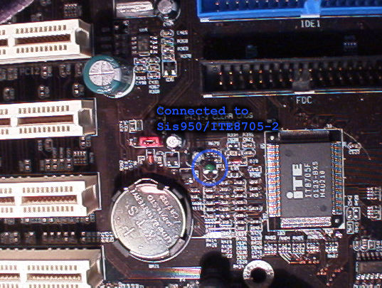
The last temperature sensor ID (SiS950/ITE8705-1) is not connected to
a temperature sensor (it gives bogus values), so you don’t use this
readout.
To get the CPU and system voltages, configure MBM5 to read from
SiS950/ITE8705-4.
3. BIOS
BIOS setup pictures (screendumps)
The following screendumps can be used as a reference when working with
the bios setup. Note that the configuration shown is neither the
default configuration nor one optimized for absolute maximum speed. It
is a "normal", safe configuration for using a 133FSB CPU
with standard PC2100 memory running Windows 2000 / XP with a PCI sound
card. Legacy ports (LPT (printer), COM (serial)) have been disabled as
well as onboard sound/game port to free up resources, and because they
were not used on that particular computer.
The bios shown is the honey X OC 021209.
BIOS
setup main page
.
Standard
CMOS Setup
.
Advanced
Setup
Power
Management Setup
.
PCI
/ Plug and Play Setup
.
Features
Setup
.
CPU
PnP Setup
.
Hardware
Monitor
.
How to reset the CMOS
Turn off your computer, unplug the power and reset the CMOS with
jumper 4. Move jumper 4 from position 2-3 to 1-2 and back to 2-3 again.
This will ensure that the current bios settings are erased and the
default bios settings are loaded on the next bootup.
Choosing the right BIOS
The newest honey X OC bioses are available in the forum header, where
you can also find some of the official versions.
The newest official bioses for the v3.x and v1.x boards are available
here
(All bioses on that page can be flashed on both the v1.x and the v3.x,
but
not
on the v5 Pro version).
The newest official bioses for the Pro (v5) boards are available
here
.
If you are running a Thoroughbred CPU on a v1.x/v3.x board and need
SSE support, you should use the
OC 021209b bios
based on the first Pro bios
. You can also use the newer modded Pro version bioses on the classic
v3.x and v1.x boards, but the 021209b version is recommended because
it has proven very stable and it uses the same PCI IRQ Routing table
as the non-pro bioses. (Windows can get confused if you change the PCI
IRQ Routing table without re-installing the OS).
Note that although current Pro bioses are (unofficially) compatible
with the non-Pro boards, non-pro bioses are
not
compatible with Pro boards.
Bios settings
A brief explanation of all the BIOS settings of the K7S5A
STANDARD CMOS SETUP
Date
Sets the day, month and year.
Time
Sets the hour, minute and second of the current date
Pri Master
Configures the master device on the primary IDE channel (usually a
hard drive). For faster boot time, set the Type option to
"Auto" and press enter. The BIOS should automatically detect
your IDE device and set its specified parameters. If it does not, you
must manually set the parameters of the IDE device. Default is
"Auto"
Pri Slave
Configures the slave device on the primary IDE channel (usually a
second hard drive, if any). For faster boot time, set the Type option
to "Auto" and press enter. The BIOS should automatically
detect your IDE device and set its specified parameters. If it does
not, you must manually set the parameters of the IDE device. Default
is "Auto"
Sec Master
Configures the master device on the secondary IDE channel (usually a
CD-ROM/-R/-RW/DVD-ROM/-R/-RW drive). For faster boot time, set the
Type option to "Auto" and press enter. The BIOS should
automatically detect your IDE device and set its specified parameters.
If it does not, you must manually set the parameters of the IDE device.
Default is "Auto"
Sec Slave
Configures the slave device on the secondary IDE channel (usually a
second CD-ROM/-R/-RW/DVD-ROM/-R/-RW drive). For faster boot time, set
the Type option to "Auto" and press enter. The BIOS should
automatically detect your IDE device and set its specified parameters.
If it does not, you must manually set the parameters of the IDE device.
Default is "Auto"
Floppy Drive A/Floppy Drive B
Configures the floppy drive(s) installed in the system.
ADVANCED SETUP
Quick Boot
From http://www.rojakpot.com:
"This feature was designed to decrease the time it takes for
you to boot up your system. But it's not the same as the Quick Power
On Self Test feature because it doesn't merely shorten or skip some
system tests just to speed up boot time. It makes use of additional
techniques to further shorten the booting process. In fact, the Quick
Power On Self Test should be considered as a subset of the Quick Boot
feature. You should enable this feature for faster booting. But if you
make any hardware changes, it is recommended that you disable this
feature so that the BIOS can run full diagnostic tests to detect any
problems that may slip through the abbreviated testing scheme offered
by this feature. After a few error-free test runs, you can reenable
this feature for faster booting without impairing system stability."
Note that K7S5A does not have a "Quick Power On Self Test"
setting, so disregard that comment.
1st Boot Device
Selects the first device the motherboard should search for an
operating system for when the computer first boots up.
2nd Boot Device
Selects the second device the motherboard should search for an
operating system for when the computer first boots up. Will work only
if "Try Other Boot Devices" is enabled.
3rd Boot Device
Selects the third device the motherboard should search for an
operating system for when the computer first boots up. Will work only
if "Try Other Boot Devices" is enabled.
Try Other Boot Devices
Allows the motherboard to search for an operating system on another
device if one is not found on the first boot device.
S.M.A.R.T. for Hard Disks
From http://www.rojakpot.com: This feature enables or disables support
for the hard disk's S.M.A.R.T. capability. S.M.A.R.T. (Self Monitoring
Analysis And Reporting Technology) is supported by all current hard
disks and it allows the early prediction and warning of impending hard
disk disasters.
While S.M.A.R.T., at first glance, looks like a really great safety
feature, it isn't really useful or necessary for most users. For
S.M.A.R.T. to work, it isn't simply a matter of enabling it in the
BIOS. You actually have to keep a S.M.A.R.T.-aware hardware monitoring
utility running in the background all the time. This means using up
some memory and processor time just to monitor S.M.A.R.T. data from
the hard disk.
That's quite all right if the hard disk you are using is highly
unreliable and you need advanced warning of any impending failure.
However, hard disks these days are reliable enough to make S.M.A.R.T.
redundant in most cases. Unless you are running mission-critical
applications, it's very unlikely that S.M.A.R.T. will be of any use at
all.
Please note that even if you don't use any S.M.A.R.T.-aware utility,
enabling S.M.A.R.T. in the BIOS uses up some bandwidth because the
hard disk will be constantly sending out data packets. So, if you do
not use S.M.A.R.T.-aware utilities or if you don't need that level of
real-time reporting, disable HDD S.M.A.R.T. Capability for better
overall performance.
Boot Up Num Lock
Sets the keyboard Num Lock at boot up.
Floppy Drive Swap
Switches floppy drive letter assignments if two floppy drives are
present. For example, A: will become B: and B: will become A:.
Floppy Drive Seek
Allows the board to search for a floppy drive at boot up. If one is
found, the board will check to see if the floppy drive is 40 or 80
tracks. Since all floppy drives are 80 tracks now, this check is
useless and it is recommend that you disable this feature.
Password Check
If you decide to use a password for your K7S5A, this feature will
allow you to change whether users must enter the password to access
the BIOS, or if users must enter the password to boot up and access
the BIOS (Setup = Must enter for setup; Always = Must enter for setup
and boot up).
Boot to OS/2 > 64MB
If you use IBM's OS/2 operating system and have more than 64MB of
physical RAM, you must enable this setting. If you do not have OS/2 (or
you have OS/2 with less than 64MB RAM) then you can disable this
setting.
L1 Cache
Enables the CPU's Level 1 Cache. Always enable this setting for faster
performance.
L2 Cache
Enables the CPU's Level 2 Cache. Always enable this setting for faster
performance.
System BIOS Cacheable
With this feature enables, a portion of the BIOS ROM is forced into
the CPU's L2 Cache. This speeds up accesses to the BIOS. However,
modern operating systems (Windows 95+) do not need to access the BIOS
since accessing the hardware via drivers is much faster and more
direct. Disable this feature to free up a portion of the L2 cache
which will yield better performance.
Graphic Win Size
From http://www.rojakpot.com:
This BIOS feature allows you to select the size of the AGP
aperture. The aperture is a portion of the PCI memory address range
that is to be dedicated for use as AGP memory address space. Host
cycles that hit the aperture range are forwarded to the AGP bus
without need for translation. The aperture size also determines the
maximum amount of system RAM that can be allocated to the AGP graphics
card for texture storage.
The AGP aperture size should be calculated using this formula :
maximum usable AGP memory size x 2 plus 12MB. The actual usable AGP
memory space is less than half the AGP aperture size set in the BIOS.
This is because the AGP controller needs a write combined memory area
equal in size to the actual AGP memory area (uncached) plus an
additional 12MB for virtual addressing. Therefore, it isn't simply a
matter of determining how much AGP memory space you need. You also
need to calculate the final aperture size by doubling the amount of
AGP memory space desired and adding 12MB to the total.
For more information regarding this subject, click
here
.
Note: Graphic Win Size is the equivalent of AGP Aperture Size.
DRAM Timing Configuration
See section 5.
SDR/DDR CAS Latency
See section 5.
SDR/DDR RAS Active Time
See section 5.
SDR/DDR RAS Precharge Time
See section 5.
Auto detect DIMM/PCI CLK
Allows the board to automatically detect the speed of the DIMM and PCI
slots.
CLK GEN Spread Spectrum
This setting reduces the EMI produced by the motherboard by reducing
the extreme values (spikes) of the motherboard's clock generator
pulses into flatter curves. This setting is best left disabled as most
users will not have problems with EMI and it could also cause system
instability... especially when in use with clock-sensitive devices
like SCSI drives.
DOS Flat Mode
Users running DOS should enable this setting as it allows DOS to use
the extended memory of the board more effeciently via memory
addressing. Users who have any other operating system should disable
this setting.
DRAM Driver Slew Rating
See section 5.[/u]
S2K I/O Compensation
Related to the drive strength signal of the Athlon processor bus and
the chipset. While this feature is best left at default, it could
possibly help with overclocking under certain circumstances.
POWER MANAGEMENT SETUP
Power Switch Type
This setting allows you to control what your computer's power button
will do when you press it. When set to On/Off, it will shut down the
machine when pressed. When set to Suspend, it will send the computer
into a suspended state in which it uses less power.
ACPI Aware O/S
The Advanced Configuration & Power Interface (or ACPI) allows the
operating system to control the power management features of the
computer instead of the BIOS. Windows 95 and above are ACPI-capable so
you should always set this option to Yes. If you have Linux, you
should set this to No as Linux does not yet have ACPI capability.
Power Management
Instructs the BIOS to control all the power management features of the
board. Set to enabled if you wish to have the BIOS keep track of power
management features.
Suspend Time Out
If there has been no system activity, this option sets the time in
which the computer will enter suspend mode in which it powers down and
uses less power (saves electricity). This option is only available
when Power Management is set to Yes.
Hard Disk Time Out
If there has been no hard drive activity, this option sets the time in
which the hard drive will power down and use less power (saves
electricity). This option is only available when Power Management is
set to Yes.
PowerOn by LAN/Ring
This setting controls the Wake-On-LAN (WOL) feature. When enabled, the
system can be automatically booted from a incoming software command
via an NIC adapter, or when an incoming fax/modem call is present.
This is useful for network administrators and people who need to
remotely access their computers. Most users will benefit from turning
this off, as it could be a potential security issue.
RTC Alarm
This setting uses the computer's real time clock (RTC) to specify a
time in which the computer will resume from power off mode. You must
use an ATX power supply in order to use this feature.
RTC Date/Hour/Minute/Second
These four options control exactly when the computer should booted up
based on its RTC if the RTC alarm is enabled.
Keyboard PowerOn Function
Allows the computer to be booted from a keyboard keypress. There are
four options:
Disabled - Keyboard PowerOn is disabled
Any Key - Pressing any key on the keyboard will boot the computer up
Specific Key - Pressing a certain key on the keyboard will boot the
computer up, and all other keys do nothing
Password - Specific keys on the keyboard must be pressed in a certain
order before the computer will boot up.
Please note that in addition to enabling this setting in the BIOS, you
must also set the jumper on your motherboard to use this feature.
Restore on AC/Power Loss
Tells the computer what it should do if there is a sudden loss of
power to the motherboard. Power off will keep the computer off until
the power button is pressed again. Power on will boot the computer up
as soon as a power supply reaches the board. Last state will return
the computer to the last power state it was in before the interruption.
PCI/PLUG & PLAY SETUP
Plug & Play Aware O/S
Enable this item if you have a Plug & Play-capable operating
system such as Windows 95 and above. Plug & Play is evolving
standard for PCs, adapters and operating systems to automatically
detect and configure hardware devices without user intervention (hence
the name plug & play; users can plug in their device and play
without having to install anything).
AGP 4X Control
This allows the motherboard to use the 4X AGP bus rate if the current
AGP card supports the 4X rate. Set it to Enabled for best performance.
Has no effect on PCI adapters.
Primary Graphics Adapter
Sets the primary display device the motherboard should use to display
graphics. If you have an AGP video card, select AGP. If you have a PCI
video card, select PCI. If you have a dual video card system, select
the bus of the card that you want to use to display the BIOS.
Allocate IRQ to PCI VGA
This will allow an IRQ to be reserved for the use of a PCI graphics
adapter. If you have a PCI video card, you should keep this setting
enabled no matter what. However, many computer enthusiasts suggest
that this also affects the AGP IRQ assignment and is best to keep
enabled no matter what bus of your video card is. That said, it's
better to keep this enabled at all times... even if you do not have a
PCI video card (it will not reduce performance to enable this if you
do not have a PCI video card).
PCI IDE Busmaster
When using DOS, enabling this setting under certain conditions can
improve IDE performance by allowing the hard drive to use DMA
transfers instead of the default PIO transfers which is signifigantly
slower. However, modern operating systems such as Windows 95 and above
include their own set of bus mastering drivers which can do DMA
transfers so this feature's benefits become null.
FEATURES SETUP
Onboard FDC
Enables the onboard floppy disk controller, or FDC. If you use the
onboard FDC, keep this enabled to ensure your floppy drive works.
Onboard Serial Port A
Enables the onboard COM1 serial port. If you do not use serial devices
in your system (e.g. serial mouse, joystick, ect.), disable this
option.
Onboard Serial Port B
Enables the onboard COM2 serial port. If you do not use serial devices
in your system (e.g. serial mouse, joystick, ect.), disable this
option. Serial Port B has the ability to manually set resources
allocated to it. Use the
Serial Port2 Mode
option to specify where allocated resources should go (Using normal,
resources are allocated to the onboard serial port itself. Using ASKIR
or IrDA, resources are allocated to the onboard IR port).
Onboard Parallel Port
Enables the onboard LPT1 parallel port. If you do not use parallel
devices in your system (e.g. printers, scanners, ect.), disable this
option. The BIOS can automatically configure this setting for you
should you chose to enable it. It can also be set manually, with three
other options to configure. The first option is
Parallel Port Mode
, which sets the mode of the port. Second is the
Parallel Port IRQ
, which identifies what IRQ the port should use. Finally, the last
option is the
Parallel Port DMA
, which identifies what DMA value the port should use.
Onboard Game Port
Enables the onboard game port for use with gaming devices such as
controllers or joysticks. Disable this option if you do not use any
such devices, or have an offboard game port.
Onboard MIDI Port
Enables the onboard MIDI port, which can allow you to hook up external
MIDI devices (such as a keyboard) to your computer. Disable this
option if you do not use any such devices, or you have an offboard
MIDI port. You can manually set the MIDI Port's IRQ by using the
option
MIDI Port IRQ
.
Onboard PCI IDE
Enables one or both of the onboard PCI IDE controllers. If you use the
Onboard IDE slots, keep this option set to "Both" to make
sure the Primary and Secondary IDE channels are both recognized and
are able to read from IDE devices.
Onboard AC'97 Sound
Enables the onboard AC'97 sound card. If you do not use onboard sound,
disable this option.
Onboard AC'97 Modem
Enables the use of the K7S5A's AMR slot. If you use an AMR modem,
enable this setting. Otherwise, leave it disabled.
Onboard LAN
Enables the onboard SiS 900 NIC. If you use a device that requires the
onboard NIC, enable this setting. If you do not use any such devices,
or you have an offboard NIC, disable this setting.
USB Function Support
Enables the use of the USB ports. If you use USB devices, enable this
item. If you do not use any such devices, disable this setting.
USB Function Support
Enables the use of the USB ports while in a DOS enviroment.
ThumbDrive Support for DOS
Allocates a small portion of memory for the USB ports if enabled.
CPU PnP SETUP
CPU Brand
(not configurable)
Tells you the brand of the processor installed in your system (this
will usually be AMD K7).
CPU Type
(not configurable)
Tells you the type of processor installed in your system, such as
Duron, Athlon, or Athlon XP.
CPU Speed
This setting actually controls two things. The first number represents
the front side bus, or FSB and the second number represents the memory
bus, or MEM. The FSB bus of an AMD K7 system is double data rate, so
that's why you see AMD CPU's being advertised as "200",
"266" and "333" FSB CPUs. But the FSB it
physically running half of that and transfer data twice per clock
cyble. That's why the numbers in the bios is half of that. Depending
on what type of processor you have, the FSB should be set to 100MHz
(all Durons, some older Athlons) or 133MHz (some newer Athlons, all
Athlon XPs). The second number represents the speed at which the
memory should run at. To determine what you should set this to, you
should contact your RAM manufacturer to find out the speed of your
RAM. For SDR SDRAM users, PC100 means you will want to set this to
100MHz, while PC133 should be set to 133MHz. For DDR SDRAM users,
PC1600 means you should set this to 100MHz, while PC2100 should be set
to 133MHz.
Setting either of the two values too high could cause system
instability or could cause the board to keep from POSTing. Make sure
you know exactly what each setting should be set to before changing
them. If in doubt, 100/100MHz should always work, and is the default
setting for the board.
When possible, you should always run the board with synchronized
speeds (e.g. 100/100MHz instead of 100/133MHz and 133/133 instead of
133/100) as the K7S5A tends to be even slower when running the CPU and
RAM async.
ADDITIONAL BIOS SETTINGS WITH HONEY X BIOSES
C000, 16K Shadow - DC00, 16K
Shadow
(Advanced Setup)
All of these settings should be disabled, as they are mainly for
compatibility purposes only.
PCI Latency Timer
(PCI/PnP Setup)
Sets the time, in clocks, for which each PCI device can hold the bus
until another device can use it. If the number is set too low, PCI
devices will interrupt their transfers unnecessarily often, which can
hurt performance. If the number is set too high, the devices requiring
frequent bus accesses may overflow their buffers, losing data.
Generally, 64 should be a good value for this setting, as it is not
too long for one device to continually hold the bus while the others
need it, but yet not too short to cause interruptions in data
transfers (most of the time). You can experiment with this setting to
determine which is best for you.
Thanks to honey X and Eric Seppanen for more information on this
subject
Offboard PCI IDE Card
(PCI/PnP Setup)
Tells the BIOS that the motherboard should use the PCI IDE controller
in the specified PCI slot.
PCI Slot 1 - 4 IRQ Priority
(PCI/PnP Setup)
Gives more priority to the IRQ of the devices in the PCI slots (note:
need to ask honey X about this and what it actually does).
I/O APIC Support
(CPU PnP Setup)
This enables/disables I/O APIC support (24 IRQs instead of the normal
16 in Windows 2000/XP). For this to work, you will have to either
reinstall Windows (recommended) or do like
this
.
Flashing the BIOS
Disclaimer: Flashing a motherboard's BIOS can be a somewhat risky
process. If something goes wrong, you will have a computer that will
not boot, and if you are in really bad luck, you will have to have the
BIOS replaced or reflashed on another computer.
The BIOSes and the Flash utility on these pages are hosted by nice
people for your convenience. But these nice people are not responsible
for the outcome of your flashing adventure. The contents of the zip
files containing the BIOSes have been checked and rechecked, but after
you have downloaded them, it is your responsibility alone. And I
cannot be held responsible for possible mis-flashes from following
this guide. The procedures are well tested, but anything can go wrong.
We live in a Murphy World.
With that out of the way, flashing the K7S5A BIOS is actually not that
complicated. Just follow the steps:
Step A, prepare a DOS boot
floppy disk
If you are using Windows 95 or Windows 98:
-----------------------------------------
Put a blank floppy in your drive and type
FORMAT A: /S [press enter]
in a command prompt window.
-----------------------------------------
If you are using Windows NT, Windows ME, Windows 2000 or Linux:
-----------------------------------------
These OS'es do not have native support for making a DOS boot floppy,
but you have the following options:
- If you are using Windows 2000, you can make a DOS 7.0(win95) boot
floppy by inserting a blank formatted floppy disk and your Windows
2000 installation CD and go to the folder [CD drive letter]:\VALUEADD\3RDPARTY\CA_ANTIV
and run MAKEDISK.BAT
Afterwards, Delete the extra programs from the floppy (see step 2 of
this guide).
- If you know someone running Windows 9x, have him or her make a boot
disk for you.
- Go to http://www.bootdisk.com and download a DOS/Win9X bootdisk
image and extract it to your floppy disk.
- If you have a CD burner and a burning program capable of burning
standard ISO images, you can also just download the ISO boot image
made by Sheppola
here
and boot on your CD drive. (select CDROM as first boot device in the
BIOS for this to work).
-----------------------------------------
If you are using Windows XP:
-----------------------------------------
Put a blank floppy in your drive, right-click the floppy icon in
explorer, choose "format" and choose "create a MS-DOS
startup disk".
-----------------------------------------
(Warning! If you use Windows NT, Windows 2000 or Windows XP and
your current BIOS is older than 01/11/09, you should create the boot
disk on another machine, because the older BIOSes have a bug that
causes corrupted files on floppy disks when using Windows 2000 or XP.)
Step B, clean up the DOS boot
floppy disk
It is important that there are no memory mangers or any kind of CD
drives etc. on the disk. To ensure this, delete everything on the
floppy disk but these files:
command.com
io.sys
msdos.sys
(Tell Windows not to hide system files or files with "known
extensions", so you can see all files on the floppy).
Step C, download the flash
utility and correct BIOS .rom file
Download the AMINF329.EXE file from the link on top of this page and
put it on the floppy disk. This is the AMI BIOS flash utility. Update:
There is also a newer version (AMINF333.EXE) available, both versions
work.
Find out which BIOS you want to upgrade to, download it, unzip it and
put the correct .rom file on the floppy. Some of the BIOS zip files on
the top of these pages have two .rom files in them, one for the LAN
version board, and one for the non-LAN version board. The LAN .rom
files have a "L" after the number to show that this is the
lan version. The non-LAN .rom files do not have a letter after the
number.
Update: The newest BIOSes have an autodetection feature so the same
BIOS can be used on both LAN and non-LAN boards, therefore there is
only one .rom file.
In some of honey X' OC BIOSes, there are two files, but it is usually
one version with AGP Fast Writes enabled (marked with "f")
and one without. If you are flashing an OC bios, you should generally
use the version without AGP Fast Writes enabled, unless you want to
experiment and know what you are doing. Have a look in the enclosed
readme file.
In the following examples, the non-LAN V.02/02/06 (020206.rom) bios
will be used. If you are flashing a newer/older or LAN bios, just
replace "020206.rom" with the file name of the bios file you
will use.
The contents of your boot disk should now look like this:
020206.rom
aminf329.exe
command.com
io.sys
msdos.sys
Step D, boot the floppy and
flash the BIOS
Restart your computer and boot on the floppy disk. (Make sure your
bios is set to boot the floppy before the hard drive, or press F8 for
the bios boot menu during the bios initialization and select boot from
floppy).
The flash utility needs to know the filename of the .rom file you are
about to flash, so you have to tell it by writing the name of the .rom
file after aminf329. In this example, I use the non-LAN
"020206.rom" file.
At the a: prompt, write:
aminf329 020206.rom
and press the Enter key.
The flash utility will check the contents of the .rom file and guide
you through the rest of the flashing procedure. When it is done, the
computer will reboot. Remove the floppy disk.
Step E, clearing the CMOS and
setting up the BIOS again
After the reboot, it will most likely tell you something like "CMOS
checksum wrong" and "CMOS battery low". This is quite
normal (for this board, anyway), and does not mean anything bad.
Turn off your computer, unplug the power and reset the CMOS with
jumper 4. Page 13 in the manual describes how it is done. (move jumper
4 from position 2-3 to 1-2 and back to 2-3 again). This will ensure
that the CMOS settings from the old bios are erased.
Plug in your power cord again and start the machine. You will most
likely get the "CMOS checksum wrong" again. It’s OK. Just
press F1 to load default values, enter the BIOS setup and set it up
the way you like it.
That’s it.
K7S5A BIOS flashing FAQ
Q1: The AMI flasher tells me in red letters: "Error 2 - File does
not exist". What's wrong?
A1: You wrote the wrong file name after "AMINF329", or
you have used a file name longer than 8 characters + ".rom".
Rename the .rom file so the name is something like "xxxxxxxx.rom".
No spaces or special characters.
Q2: I am trying to flash my BIOS but I keep getting the error "chipset/flashpart
isn't available."
A2: You are trying to flash the BIOS from a command prompt shell
within Windows. You need to boot to pure DOS mode to have access to
the BIOS
Q3: My girlfriend/boyfriend/dog disconnected the power to my computer
by accident while I was flashing my BIOS. My computer is now dead.
What can I do?
A3: If you are a little lucky, the "bootblock" code in
the BIOS still works. This will allow you to flash your BIOS even
though you computer seems dead. Format a blank floppy (on another
computer, of course), and put the .rom file on it, and nothing else.
Now rename the .rom file to this name: "amiboot.rom". Put
the disk in the dead machine and turn it on. Wait for a couple of
minutes (now would be a good time for a little prayer) and listen for
four beeps. If you hear them, the bios on the floppy has been flashed
onto your BIOS chip. Turn the computer off and on again, and it should
work again.
Q4: My BIOS upgrade went bad, I tried the "amiboot.rom"
trick, but it did not work. Is it time to give up?
A4: If you have a steady hand, a friend with a K7S5A and he is
willing to let you borrow his BIOS chip for half an hour (with the
possibility you will mess that one up too), there is a last option: A
BIOS
Hotswap
. Be sure you know what you are doing before you start.
I did this once with two Aopen boards, and it worked.
Otherwise, you have know someone with a flash EEPROM programmer, who
can flash your bios chip for you.
Q5: My onboard LAN will not receive an IP via DHCP (and similar
problems) after I flashed my bios, what happened?
You have probably lost your MAC address. It happens sometimes when
you flash the bios. You can use this little utility to restore it:
ftp://ftp.ecs.com.tw/bios/flash/k7s5a_id.exe
There is a readme file enclosed that explains how to do it
How to modify the default settings in a BIOS .rom file
WARNING!! You should not perform the following unless you really
know what you are doing. Flashing your own modified bios .rom file
could make your system unbootable if you change the wrong things.
To edit a K7S5A AMI bios file, you need the utility
"AMIBCP75.EXE". You need to run it in pure DOS mode. You can
find AMIBCP75 on
Polygon’s
Rebels Haven K7S5A bios download page
.
Make a directory on your "C" drive (call it, let's say, 'MODBIOS'),
and place the unzipped BIOS to be modified, along with the BIOS tool,
in this case AMIBCP75.EXE, in it.
Using a WIN95 or WIN98 boot disk, re-boot to the boot disk.
I'm assuming that in the present BIOS settings you've set the floppy
as the 1st boot drive.
If you didn't, press F8 as the computer posts and you will go to CMOS
Setup menu.
Arrow down to the second option and select the floppy drive as the
"first boot device".
Once you are up in DOS, get into that directory ('MODBIOS') you made
in step 1
Type AMIBCP75 xxxx.rom where xxxx.rom is the name of the BIOS you want
to change
After loading the 'MODBIOS' folder as suggested above, arrow down to
"Configure SETUP Data" and press 'Enter'
You now have 7 selections:
---Standard SETUP
---Advanced CMOS SETUP
---Chipset SETUP
---Power Management SETUP
---PCI/PnP SETUP
---Peripheral SETUP
---Hardware Monitor SETUP
Advance CMOS SETUP has the majority of the options that I like to
preset, but go to each window and just have a look around.
Standard SETUP mainly allows setting the drive info. I always leave
them all on "AUTO"
You won't actually CHANGE anything in the BIOS until you either you do
a 'Save', or the program asks if you want to save when you try to exit,
and you say 'YES'.
You hit escape to go back 1 window.
Use the arrow keys to go to the setting you want to change.
Use the arrow keys and page-up or page-down to change that setting.
Each option can be made active, or not.
When made 'active' they will be visible in your normal CMOS setup, and
you can then change them, if you chose to, in your normal CMOS setup.
I always leave the rights on "both".
The settings for Optimal and Failsafe can be set to the 'Defaults' you
want for your CMOS settings.
'Optimal and Failsafe' are often the reverse of what you think they
should mean, so don't mess with that aspect until you're certain which
is which.
I always set them both the same way because the names of these are NOT
consistent with what you see when entering the CMOS setup by pressing
delete on boot-up.
When you're done, press escape until the program asks if you want to
save or not.
Then flash the modified .rom file to your bios chip using the normal
flashing procedure.
4. Troubleshooting
RMA or not?
A certain percentage of motherboards produced are in some way faulty
and some of them will end up in the hands of end buyers in a faulty
state. This goes for any motherboard manufacturer and shouldn't come
as a surprise to anyone. But of course different manufacturers/models
have different fault percentages. There have been lots of discussions
in this forum as to if ECS' end user fault percentage is bigger than
it's competitors.
I do not have the statistical data to conclude anything on this
matter, but the K7S5A is
the
cheapest socket A DDR platform available, and have been that for a
very long time. To maintain the very low price, ECS must do something
different than it's competitors, and that something could be for
example less profit, cheaper components or less efficient quality
control among many other things.
Bottom line: If you are working on an unstable/non-working system and
you have done a reasonable amount of troubleshooting to rule out that
other components are to blame,
do not hesitate to RMA the board.
Distorted sound when using a PCI graphic card
The problem can be fixed by flashing the 020626 bios. (You only need
to do it if you use a PCI graphic card).
Also, make sure you are using the newest drivers for your soundcard or
onboard sound.
Secondary IDE drives are not detected at bootup
If you are experiencing this problem and you are using a Netgear FA311
network card, you should take it out and use a different one (anything
but the FA311 should work). There is a well-known compatibility /
conflict issue with the FA311 and the K7S5A. More info
here
.
System will not POST
There can be a number of possible causes for this (for example a case
short, bad component/card/cpu, bad bios configuration etc.), so to
rule out as many factors a possible, take the board out of the case,
reset the cmos and put it on a non-conductive surface and add only the
minimum number of components needed to post: CPU+heatsink/fan, one
stick of memory, a graphic card+monitor, the power on switch, the
beeper and the power supply.
System randomly unstable. System works only at fsb/mem
100/100. System crashes after some time running full load
Instability (lock-ups, freezings or reboots, often when running
graphic intensive games or system demanding applications) is often
caused by one or more of the following things:
Power supply is too weak or low quality.
Some K7S5A boards are unable to use two PC133 SDRAM sticks at the
same time at 133MHz.
CPU, system or chipset overheating.
Defect or semi-defect components (board, memory, graphics card
etc.)
Bad, missing or old device drivers
Power supply is too weak or low quality:
Check the power supply. It should have a 3.3v and 5v line combined
output of at least 180 watt. Read "Power supply
specifications" in section 1 for more info.
Some K7S5A boards are unable to use two PC133 SDRAM sticks at the same
time at 133MHz:
Use only one stick of PC133 memory or use DDR memory instead. (not
really a solution, more a work-around).
CPU, system or chipset overheating:
The first thing to do is install a monitoring program such as
Motherboard Monitor which will allow you to continuously watch your
temperatures and see where, when or at what temperature problems
occur. It will also give you visual proof of any improvements you
make. MBM5 can provide a text log of temps and also, your voltages.
MBM5 monitors both the CPU and system temperatures and can also be set
up to monitor HDD temps if you wish to.
THE CHIPSET.
(Note that there will be situations where a (small) modification to
the original setup of the board like the heatsink fix would be
problematic, if for example you are considering an RMA. In theory, it
will void your warranty, because it is a physical modification to the
board.)
The SIS chipset, located on the board below the CPU, has a small
orange heatsink. This is attached to the chip by means of double sided
sticky tape which does not conduct heat very efficiently. The tape
should be replaced by a proper thermal compound. To do this, first,
run the system for a few minutes to warm the chipset up. Switch
everything off, grasp the heatsink and twist it gently - it will come
away from the actual chip very easily. Thoroughly clean the heatsink
and the top of chip taking care not to damage either. Spread a small
amount of thermal compound on the chip (keep two corners clean) and
put two SMALL blobs of superglue there. Place it in position and hold
for a couple of minutes until the glue sets.
You can also use a thermal adhesive (heat-conductive epoxy) to attach
the heatsink without the use of thermal paste. If you plan to
overclock a lot, or just want to be on the really safe side, you can
also choose to mount a bigger heatsink, for example an old 486 or
Pentium heatsink. This modification can be further enhanced by adding
a small fan to the heatsink.
Often this modification on it's own is sufficient to solve the
problems. More info
here
.
THE CPU
Excessive CPU temperatures are best avoided. The CPU will hang at
around 60+ degrees C. So you would want to keep it below 50-55 C. It
is important to ensure that you have an efficient CPU cooler- not all
CPU coolers do the job very well, so choose one with care. A large
cooler with a 80mm fan spinning at medium speed is a better choice
than a small cooler with a fast-spinning (and thus noisy) 60mm fan.
Ensure when installing the CPU that a thin layer of good quality
thermal compound is used between the CPU and heatsink.
All of the above is important but if the environment surrounding the
CPU and Chipset is excessively warm then the beneficial effects of
efficient CPU and Chipset cooling will be minimized.
THE SYSTEM/CASE
This is where most reduction in temperatures can be achieved. First,
ensure that all cables and ribbon connectors are neatly tied so as not
to impede the airflow around the CPU etc.
Next, look at the fans already fitted to your case. Most cases come
with a rear mounted extractor fan, usually mounted near the top under
the PSU. If you don't already have one at the front, fit an input fan
at the bottom front of the case. In addition many users have mounted a
fan on the side, opposite the CPU, to feed external cool air directly
towards the CPU fan - often with ducting to further improve the
flow.Also ,some have added top mounted ( ie: in the roof of the case)
extractor fans. A good target is to try to reduce the case temperature
to as near as possible to the ambient room temperatureThis will make
it much easier to keep the CPU and Chipset cool, which is, after all,
the whole purpose of this exercise.
OTHER THINGS THAT HELP
A dual fan PSU (one with an input fan on the bottom and output to the
rear) will help pull more warm air out of the case.
Seperate your Hard Drives. - If you have two HDDs, try to seperate
them by putting one in a spare CD ROM bay rather than stacking them
tightly together. Doing this will not only help stop the build-up of
heat generally, but will keep the actual HDD temperatures down.
Ensure that your system case is in a position that allows air to
circulate easily around it. Make sure that none of the ventilation
grills are covered. Also, place it in as low a position as you can. In
a normal heated room, the temperature will usually be 1 or 2 degrees
cooler at floor level than it will be at a height of 1.5 metres.
AFTERCARE
When you have done all of the above and your PC is running smoothly,
allowing you to run complex games for hours on end, it is important
not to forget that your system needs occasional aftercare. The BIGGEST
enemy is dust. The more air that goes through your case, the more dust
gets trapped in there.
Depending how much you use your system, make a point of opening the
case and cleaning the fans and, in particular the Chipset and CPU
heatsinks. In the space of a few weeks, even in the cleanest house, a
large amount of dust can accumulate and dust is a very good insulator
.A gradual build up of dust can lead to a gradual deterioration of
your cooling system and so to a loss of system performance and
stability.
Bios (cmos) settings lost on startup
There have been, and continues to be, reports about CMOS settings
being repeatedly lost on some boards. It can be quite annoying, and if
the first "simple" solutions (described later in this
section) do not remedy the problem, you should consider an RMA.
Symptoms of lost CMOS settings:
When you power on the computer, the message "Checksum wrong"
is shown. You will be offered the option to continue, load bios
defaults or enter the bios setup. After you have configured the bios
options again, the CMOS will retain the settings for a number of boots
until it happens again.
The cause for this behaviour has not determined 100%, but you can try
a number of things to fix it:
1: Cleaning the CMOS battery contacts and tightening them (carefully)
to ensure a good contact.
2: Changing the battery.
3: A rather more adventurous cure is the "resistor fix",
full details of which can be found
here
and
here
.
Blank screen after POST
The following things can cause this:
(A) The OS was installed on another system. You need to do a fresh OS
installation.
(B) Your board detects ghost DDR memory. More info
here
.
(C) IDE drive conflict. Check your master/slave/primary/secondary and
bios config.
Keyboard not working during POST
This has been reported with some K7S5A Pro boards. Try to clear the
cmos. If you use a USB keyboard, try one with a PS/2 connector. If it
still doesn’t work, RMA the board.
Bios error codes (beeps)
When you turn on the power to your computer, it will perform a Power
On Self Test, or POST. The POST will generates beeps through the PC
speaker to alert users of errors. Certain combinations of beeps can
signify different errors that occur during the power up sequence.
Unfortunately, many motherboard manufacturers do not include what
these combinations of beeps mean. Here is a basic list of the beep
combinations and what each of them mean.
(Note: This list is the default error code beeps of a basic American
Megatrends, Inc. BIOS. Some of these combinations of beeps or error
codes may be slightly different from the K7S5A combinations of beeps
or error codes.)
(Note 2: A single beep after the POST usually denotes an "error
free" system and is not a problem. However, if you hear
additional beeps after the first, something may be wrong.)
1 Beep - DRAM Refresh Failure
The system is having problems accessing the system memory so it can
refresh it. Refreshing is performed on all system memory to keep its
contents active.
Recommendations
Troubleshoot the motherboard (use this guide)
Check the RAM for errors using a memory test (e.g. Memtest86)
Check the power supply
Check for system overheating
RMA the motherboard and/or RAM
2 Beeps - Parity Circuit Failure
The parity circuit is responsible for generating and checking the
parity bit on the system memory when parity checking is used. This
circuitry is not working properly. Usually this means either the
motherboard or the system memory is not working properly. However,
K7S5A boards seem to use 2 beeps to signify a CMOS or low battery
error.
Recommendations
Troubleshoot the motherboard (use this guide)
Check the RAM for errors using a memory test (e.g. Memtest86)
Check the power supply
Check for system overheating
Check for a low, degraded, or deteriorated CMOS battery
Check this guide's Lost CMOS settings section (K7S5A only)
RMA the motherboard and/or RAM
3 Beeps - Base 64K RAM Failure
This indicates that there is some sort of failure within the first 64
KB of system memory. Usually this means there is a bad stick of RAM in
the first bank, although this is not always the case.
Recommendations
Check the RAM for errors using a memory test (e.g. Memtest86)
Check the power supply
Check for system overheating
RMA the RAM
4 Beeps - System Timer Failure
This indicates that there is a problem with one (or more) of the
timers used by the motherboard to controls its functions.
Recommendations
Troubleshoot the motherboard (use this guide)
RMA the motherboard
5 Beeps - Processor Failure
This indicates that the processor is generating an error condition.
However, this does NOT mean that the processor is dead (if that were
the case, the system would not boot at all). Sometimes the motherboard
can cause this error as well.
Recommendations
The processor is mostly likely to cause these errors, so check for
overheating problems, especially above or around the CPU socket. If
the system is relatively cool, try reducing the FSB of the CPU,
disabling the L2 cache, or using less aggressive BIOS settings. That
said, if any of the conditions stated above are the solution to the
problem, then you should seek an RMA or a refund on your processor.
Processor errors are VERY uncommon in these days and if your processor
generates BIOS failures straight out of the box (or even after a month
or so of use, as long as it is not abused) it usually means you have a
bad chip and will not work well or at all.
Troubleshoot the motherboard (use this guide)
RMA the motherboard
6 Beeps - Keyboard Controller Failure
This indicates that the controller which is used to communicate with
the keyboard has failed or is damaged. Furthermore, it also controls
the A20 gate that provides access to the high memory area.
Recommendations
Check that your keyboard is properly inserted into the keyboard port
and that the pins on the connector are not damaged, bent, or missing
Check the motherboard for damaged chips or circuits (usually the chips
or circuits will looked crushed or burnt)
Troubleshoot the motherboard (use this guide)
RMA the motherboard
7 Beeps - Virtual Mode Exception Error
This indicates that virtual mode (one of the different modes that the
processor can run in) is generating an error during the POST. Usually
the processor causes this error, but sometimes the motherboard may
cause it as well.
Recommendations
See "5 Beeps - Processor Failure" recommendations.
8 Beeps - Display Device Failure
This indicates that there is a problem with the video card, the video
card's memory, or both. Also, the video card may not be seated
securely in the AGP/PCI slot or there may not be a video card in the
motherboard at all. This error is "non-fatal," so the system
may continue to boot even after the error has occurred.
Recommendations
Insert a video card into the motherboard
Firmly seat the video card into the AGP/PCI slot
Troubleshoot the video card using a video card stress test/benchmark
(e.g. 3DMark2001; a 3D-intensive game)
Check for system overheating (especially above or around the video
card)
RMA the video card
9 Beeps - CMOS Checksum Failure
This indicates that the checksum value (data that contains correct
BIOS ROM code) has checked its value against those of the BIOS's ROM
and they were mismatched or incorrect. (Note: This is NOT the same
thing as a BIOS Checksum Error, a problem that seems to frequently
happen on K7S5A motherboards.)
Recommendations
Replace the BIOS ROM chip on the motherboard
RMA the motherboard
10 Beeps - CMOS Shutdown Register Read/Write Error
A component of the motherboard is producing an error which is
interacting with the CMOS memory.
Recommendations
RMA the motherboard
11 Beeps - System Memory Cache Failure
This error code is no longer relevant since the L2 cache is now
located on the processor's die.
Continuous, Abnormally Loud or Random Beeping
This usually indicates there is a problem with the RAM or the
motherboard itself.
Recommendations
Troubleshoot the motherboard (use this guide)
Check the RAM for errors using a memory test (e.g. Memtest86)
Swap the "problematic" RAM stick(s) for a RAM stick that is
known to work properly
Check for system overheating
RMA the motherboard and/or RAM
SSE disabled when using Thoroughbreds
Look in the CPU support section of this guide.
ACPI in Windows 2000/XP
Coming soon / anybody want to write a few lines?
5. Overclocking
DDR bus speeds explained
Coming soon / anybody want to write a few lines?
Relationships between FSB, PCI and AGP
Coming soon / anybody want to write a few lines?
FSB overclockning (with honey X OC bioses)
Coming soon / anybody want to write a few lines?
FSB overclockning (with software)
You can change the FSB from within Windows with a few different
software utilities. The following shows how to do it with the program
CPUCooL. You don't have to use an OC bios to change FSB with software,
but note that the machine will only run with the software selected FSB
speed until you reboot the computer. For a "permanent" OC,
you have to flash an OC bios.
Also note that the only way to reach 166/166 on the K7S5A is by
software overclocking. Due to a PLL bug, it can't boot at 166/166.
You can download CPUCooL
here
.
When you are installing it, set it so that it loads with every Windows
start-up.
Reboot
First thing it asks when it comes up for the first time is "Which
mobo & Model"
You need to select the motherboard brand, version etc., before you can
use it to change the FSB, which is what we want to do, first and
foremost
Your "Mainboard" is ECS and "Mainboard type" is
K7S5A...(Doh!),
Your PLL is the ICS type: 9248(ABC)F-199... you can check that by
reading the #'s on your PLL chip (go back to Podien's site for info on
how to locate it on your mobo)
Now, click "Functions"> "Change front side
bus/change CPU speed"
Start clicking on the tiny little 'up' arrow, to the right of
"Tray frequency 1" until it shows an FSB of 137.3/ PCI 34.4
/ RAM 137.3
Go to "Tray frequency 2" and take it up to 142.7/35.7/142.7
Go to "Tray frequency 3" and take it up to 146.7/36.7/146.7
Forget about entering the 150/30/150 option in the next line because
the ONLY way to get to a 150 FSB is straight from an OVERCLOCKING bios
set to boot at 150.
Go to 'Tray frequency 4 and take it up to 166.7/33.3/166.7
I'm assuming in the above that you are using an Athlon of the 133/266
FSB persuasion here... if you're using a Duron you'll need to use the
lower sets of matched numbers like 103/103, 107/107, 110, 112, 124.
Click 'OK', and reboot to temporarily 'lock' these frequencies into
CPUCooL
Assuming you told CPUCool to start with every windows start, there
should now be a new icon beside your clock in the system tray.
Right-click on it to open the Main Display
Right-click on it again, and then click the lowest "FSB:
137MHz"
What's CPUCool showing your processor speed at now?
Use either of WCPUID or SysID to verify, if you don't want to believe
what CPUCool is showing you in the "Main Display" window?
(If you go into Display Options> This Display (Main Display)>
Graphic display and check the box at lower left, it will graphically
show the speed)
While you're in there, check whatever else you'd like to see
graphically displayed.
WCPUID is available free here www.h-oda.com/
SysID is available free here www.sysid.subnet.dk/
Keep going up the FSB "string" in the little pop-up window
that you to created until the comp 'locks' the moment you click on it.
When that happens, just unplug your computer and then Restart it and
Bingo! You’re back to 133.
Tuning memory timings
Changing memory timings can be very helpful when overclocking as it
increases the overclocking headroom of the RAM. In fact, sometimes
just changing the memory timings may allow a user to overclock higher
than the specified speed of one's RAM. Here's a brief explanation of
what each setting does, and the recommended setting for
overclocking/stability and RAM bandwidth/overall speed.
DRAM Timing Configuration
DRAM Timing Configuration offers little in the sense of performance
gain, but may help in curing memory problems. With some memory
modules, the timings of the modules are not correctly identified using
the SPD (Serial Presence Detection). In some cases, this setting can
be used to tell the BIOS approximately how fast the module is and what
the timings for the module are. However, most quality memory modules
that are produced today work just fine with SPD.
Recommended settings:
For overclocking/stability = Safe
For RAM bandwidth/overall speed = Ultra
CAS Latency
CAS Latency controls the time delay (in clock cycles) that passes
before the SDRAM module starts to carry out a read command after
receiving it. It also determines the number of clock cycles required
for the completion of the first part of a burst transfer. In other
words, the lower the latency, the faster memory reads can occur.
However, some memory modules cannot handle such low latencies and may
lose data, resulting in a system crash/failure. Most memory modules
also have something called SPD, or Serial Presence Detection, which
automatically determines the specified CAS latency of the memory
module.
Recommended settings:
For overclocking/stability = 3T
For RAM bandwidth/overall speed = 2T
RAS Active Time
Low figures will improve performance.
Recommended settings:
For overclocking/stability = 6T
For RAM bandwidth/overall speed = 4T (with HX OC BIOS)
RAS Precharge Time
RAS Precharge Time sets the number of cycles required for the RAS (Row
Address Strobe) to accumulate its charge before the SDRAM refreshes.
Reducing the precharge time to 2 improves SDRAM performance. However,
the precharge time of 2 may be insufficient for some SDRAM modules. In
such cases, the module may not be refreshed properly and it may fail
to retain data. This may cause a crash or system lockup/freeze.
Recommended settings:
For overclocking/stability = 4T
For RAM bandwidth/overall speed = 3T (2T with HX OC BIOS)
DRAM Drive Slew Rating
DRAM Driver Slew Rating affects the performance of DDR SDRAM. Set this
setting to "Fast" for a slight performance gain.
Recommend setting:
Always set this to "Fast" if you have DDR SDRAM.
Memory Termination
Memory Termination was introduced in the 020626 BIOS by ECS, and is
assumed to be a fix for the ghost memory problem--the motherboard
thinking it had more RAM installed than it did (shows up in the POST
screen as module 0,1 for example).
Recommended setting:
None, leave it at the default setting.
Of course, there are exceptions and notes that should be heeded when
tweaking RAM timings.
First of all, FSB speed should always take priority over aggressive
memory timings. For example, if one has the option of having lower
memory timings or raising one's FSB by a few MHz, the latter option
should be done. An increase in FSB speed will almost always yield
better bandwidth (and overall system speed) than lowering RAM timings
will.
The ultimate goal of tweaking RAM timings (if any) is to obtain the
most aggressive RAM timings at the highest possible speed with no loss
of system stability. If your RAM is fast enough to handle the
aggressive timings and faster FSB, then go for it. As long as your
system stays rock stable, there's no real need to use the less
aggressive RAM timings. In fact, the only real time you should NOT use
faster RAM timings of course, there is always an exception) is when
you are having system stability problems and you know it is definitely
because of the RAM... and nothing else.
Changing multiplier
The K7S5A does not support manual multiplier adjustments from the bios
or via jumpers. To change the multiplier, you have to modify the CPU:
Look
here
if you have an Athlon Thunderbird / Duron Spitfire
Look
here
if you have an Athlon XP Palomino / Duron Morgan
Look
here
if you have an Athlon XP Thoroughbred
If you are using a Palomino, Thoroughbred or Barton CPU, you can also
change the multiplier by wiring the right CPU pins together (more info
here
) or putting small U-shaped pieces of wires in the right holes in the
CPU socket. Once again, Ocinside.de explains
exactly
which pins/socket holes you should use
.
Changing Vcore
The K7S5A does not support manual voltage adjustments from the bios or
via jumpers. To change the Vcore, you have to modify either the
board
or the
CPU
.
|