
LET THERE BE LIGHT
In the previous Fact Sheet No 4 we discussed the ways we can calculate different values in electronic circuitry. This time we follow this up with a design for a simple, yet useful gadget: an LED (light emitting diode) tester. This one uses a couple of cheap parts and you can build it easily. We will also see how the knowledge from the last Fact Sheet No 4 now can be applied. (Skip the mathematics if you like.)
An LED is a diode that emits light. LEDs are reliable, last a long time and can be used in many different ways. They must, however, a) be connected with the correct polarity and b) have a resistor in series that limits the current.
In the circuit is a diode. While this is not really necessary, it will protect the LED should you ever accidentally connect the battery the wrong way. Diodes are 'one-way streets' in electronics. If the battery connections are reversed, no current will pass through the diode and therefore protect the LED.
For building the tester you will need the following parts: a wooden board, around 10 to 15 cm square, some staples or short nails, some wires, an LED, a resistor of 390 Ohms, a small 9 V battery and, if you like, a simple small diode.
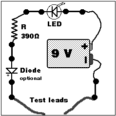
You can build this tester by following the drawing. It will make it easier if you can print the drawing - or get it printed for you - and glue it onto the board. For the dots you can use the staples or nails, hammered half-way into the wooden board. Then you attach the different parts as shown. If you can solder them in, that is fine; otherwise make sure the connections are very solid. Attach two insulated wires to the test terminals and, if possible, connect probes or crocodile clips to the ends.
The path that the current takes goes like this: (Let us assume that the part to be tested is conducting.) From the negative terminal of the battery it passes through the part under test, then the protection diode and the current-limiting resistor. The diode lights up and completes the circuit to the battery.
If you want to make sure that the tester itself is in working order, briefly touch both test probes together and the LED should light up.
HOW TO USE IT.
You can test all sorts of equipment such as loudspeakers, coils or maybe long wires to find out if they conduct or not. When the LED lights up, you have continuity. That means the part is conducting and, in most cases, the part is ok. On the other hand, if it lights up when you test a capacitor it means it has in internal short and is damaged. Capacitors do not conduct DC.
How do we calculate the value of the resistor? The current that the ordinary LED uses is 25 mA (0.025 A !). Take the formula from the last Fact Sheet No 4: R (Omega) = V divided by A. 9 over 0.025 gives us 360. For extra safety we use the next higher value which is 390 Ohms. Simple, isn't it.
In our next, Fact Sheet No 6 we will find out how we can make sure this tester is reliable.
Return to Electronics index
page
Copyright® 1997-2003 Peter Schmedding, Child Development
Projects, Canberra, Australia.