In common with all the later Spitfires,
Seafires,
the Spiteful
and the Seafang,
Supermarine's first jet fighter, the Attacker, was
designed at
Part
of
the drawing office staff at
Further
items were as follows. Armament: Standard
R.A.F. four-cannon installation, but with sufficient ammunition for fifteen
seconds continuous fire from each gun (the same as for the Spiteful). Tankages: 300 gallons, plus provision for an outsize
270 gallons drop tank. Also dive recovery flaps, and a sealed cockpit with
a 3 ½ lb.
differential pressure.
Only a small design team could be spared for the Attacker
due to the pressing demands for improvements and modifications on machines
already in production, but construction of a few minor parts, and jigging
up, did begin about two months after design started. In fact, having in mind
the tremendous pressure of work then being coped with by Hursley's
strictly limited staff, and that the whole works was shifted bodily from the
bombed-out Southampton location during a critical phase of the war, it is
amazing that the flow of new marks and types for the R.A.F. and Royal Navy
never showed signs of drying up.
First flight
of the Attacker prototype, TS 409, was on
Converting
the Attacker for Navy use has meant, as always, the altering and addition
of a number of details, but first we'll mention two changes to the second
machine which have nothing to do with its intended use as a naval fighter.
The Attacker
takes in air for the engine through large ducts on either side of the cockpit,
and so as to increase intake efficiency, turbulent air next to the aircraft
skin is skimmed off separately, finding its way on the first machine into
the belly of the aircraft where a louvre is provided
for its exit. This arrangement has been tidied up for machine No.2, on which
the boundary layer air is directed smartly to exit grilles just aft and above and below the main intake. Thus the tired air
is got rid of quickly and neatly. Incidentally, the boundary layer intakes
have since been faired in on TS 409 in order to assess their exact value,
and the result has been a slight but noticeable reduction in performance,
due solely to the added congestion in the air ducts.
A second
minor change to the basic machine introduced on TS 413 is that a steerable double tail wheel is fitted. That on the first machine
was a non-steerable type which had the double wheels
revolving on a common axle. Due to the rake of the supporting leg, one of
the wheels lifted partially off the ground in a turn, scuffed along, and made
steering (with the brakes) difficult. On the second machine, the double wheels
are fitted with a differential axle, and are moreover adjustable to three
conditions: fully castoring (360°); locked central;
or steerable from the rudder six degrees either
side.
While discussing
tail wheels and steering, we might mention the fact that the rudder on the
Attacker, as on any pure jet type, is practically useless for steering while
taxying due to the absence of slipstream from a
propeller. The Attacker can be taxied quite fast with the rudder flapping
wildly from side
to side
and deviate scarcely an inch from its path. The absence.of
slipstream, too, is the reason for the ten degrees forward-rake of the top
lip of the jet outlet-about 250 lb. . pressure
is exerted by the jet on the bottom lip, and serves to keep the tail hard
down when running up or taxying.
Turning
to naval gear, the second Attacker has a vee-frame
hook near the extreme tail; presumably the presence of the tail jet pipe precludes
the use of a sting-type hook as on the Seafang.
Also, Seafang undercarriage legs with longer shock-
absorber travel are fitted to compensate for the greater shocks of deck landings.
The retracting mechanisms of these are so arranged that the legs shorten as
the wheels move up, and so are accommodated within the length of the existing
housing.
Accelerator
fittings on the Sea Attacker are of the latest type to be used by Naval Aviation,
and are similar to those used by the U.S. Navy, replacilig
the old catapult trolley and aircraft spool gear. Accelerator hooks are mounted
in the wheel bays, and from them cables lead forward over pulleys ili the deck and down to cordite
charges in the bowels of the carrier. Burning of the cordite exerts a growing
tension on the cables, tending to pull the aircraft forward. The aircraft
is held in place by hold-back gear at the tail until the mounting force snaps
the linkage and the machine is shot forward and into the air.
Provision
of R.A.T.O.G. caused some minor headaches, since no less than eight rockets
were called for. After various schemes had been discarded, the rockets were
finally arranged two above and two below each wing so that the resultant thrust
forces were inline with the aeroplane C.G. The blast of eight rockets should
get the Attacker off the deck in double quick time, but from a visual examination
the airframe structure looks more than tough enough to withstand even this
tremendous stress.
The specification
E.10/44 mentioned that full consideration must be given to safely evacuating
the pilot at all speeds. It was logical, then, to use an ejector seat. Vickers
installed their own design of seat in TS 409, and
it proved completely satisfactory. Subsequent machines have the Martin Baker
seat, now standardised for the R.A.F., and in the case of the Attacker this
seems rather a pity, for the Vickers seat is some 40 lb. lighter.
Structure
of the Attacker is massive, and we formed the initial impression that the
machine would be on the heavy side. For example, the nose section is a heavy-gauge
shell, half an inch thick in places and with only an apology for internal
stiffening, while elsewhere the skin and some of the frames are immensely
strong. Yet in actual fact the Attacker is, at 11,300 lb. normal all-up weight,
little heavier than the rather smaller Seafang.
As distinct from the logical, workman-like layout, there
are a number of intriguing design details built into the Attacker;
the spring-out pilot's footstep is an example, and also the ingenious disposition
of fuselage tanks about and between the air intake ducts. Provision for radio
servicing is also rather clever, although it exis~
only in mock-up form as yet. The main set is to be housed in the nose above
the bottom access door, and may be pulled down on counter- balanced telescopic
arms and released at one side to hang loose beneath the nose, completely exposed
for servicing. The usual transmitter-receiver and I.F.F. sets fitted (TR.
1464 and R. 3212 were specified) are at present mounted on ordinary fixing,
or are taken out to make way for the camera and auxiliary instrument panel
of the automatic recording equipment.
The whole engine bay, or plenum chamber, is exposed by removing
the compartment ct>ver, which is tightly sealed
in flight, like the cockpit canopy, by pneumatic rubber tubing, so that in
effect the whole bay is pressurised. During running
up or taxying, a temporary depression is likely
to set in inside the bay, so that extra intakes are provided in the compartment
cover which are sucked inwards to admit air when
subnormal internal pressures obtain. Another feature of the installation is
the volute bleed around the jet pipe, fitted to break down the harmonic fluc- tuationswithin ihe jet pipe which sometimes cause starting difficulties.
The volute bleed is operated via a Teleflex cable from a handle in the rear
starboard fuselage side. The tail pipe, by the way, expands as much as It
in. in length at full engine power and so is mounted on special hinged linkages.
The overall impression we received from the design staff
and from seeing the actual machine is that the Attacker has enormous potentialities
for further development. The third machine will have various (unspecified)
improvements, while a forth has all surfaces swept back 45 degrees or more,
and in either form a determined attack on the air speed record could be made.
Even at present, the Attacker is among the fleetest jet fighters in the world;
with a few mOre months' development it should become
a world-beater.
The jet engine itself is a Rolls-Royce Nene
I, which gives 5,000 lb. thrust at 12,300 maximum revs., weighs 1,550 lb.
(less jet pipe), consumes fuel at the rate of 1.065 lb./lb./hr. at full power,
and measures 49}; in. in diameter. Engine accessories are mounted remotely
around the top of the air intake" gramophone horn", driven by a
common shaft which may be readily disconnected in the event of removal of
the engine. Incidentally, removal of the long tail pipe requires a special
jig consisting simply of a long, trolley- mounted, horizontal bar which is
run right up the jet pipe. The pipe is then disconnected and rests on padded
supports along the bar, which is then withdrawn with, tfte-"-jet
pipe threaded neatly over it.
Normal fuel capacity is a shade
over 290 gal., giving a range of 410 miles, but a 270-gal. belly
tank is available which boosts the range to 1,100 miles.
ATTACKER
LEADING PARTICULARS
Dimensions
Span 36 ft.
II in.
Length
37 ft. 6 in.
Maximum height, tail down 9
ft. II in.
Wing area
226 sq. ft.
Weight and Loadlngs
All-up weight-normal 11,300 lb.
Engine Installation
One Rolls-Royce "Nene"
engine 5,000 lb. static thrust
Capacities
Fuel tanks: Total Internal capacity. 290 gal.
Auxiliary jettisonable
tank 270 gal.
Armament
Four
20 mm. Hispano guns
PERFORMANCE DATA
(Under I.C.A.N. conditions)
Level
Speeds (combat rating
at 95% of normal all-up weight)
Sea level 590 m.p.h.
10,000
ft. 583 m.p.h.
20,000
ft. 561 m.p.h.
30,000
ft. 538 m.p.h.
Rate of Climb (combat rating at initial weight of 11,300
lb.)
Sea level-6,600 ft./mln Time
to height mins. 0
10,000 ft. - 5,600ft./mln 1.64 min.
20,000 ft. - 4,500 ft./mln
3.61 min.
30,000 ft. - 3,280 ft./min 6.17 min.
Operational
Ceiling
48,500
ft.,I.e. height at which
the rate of climb becomes 500 ft./min.
Range
and Duration
Range
at 30,000 ft.
Average
cruising speed. 380 m.p.h. 392 m.p.h.
Miles
per gallon 2.94 2.76
Duration of cruise 1.08 hrs 2.81 hrs.
Total
distance 410 miles 1,100 miles
Endurance at 30,000 ft.
Maximum endurance 1.6
hrs 3.78 hrs.
Note. - The ranges and endurances
quoted above include
allowance for 2 minutes at take-off power, climb to
30,000 ft.,
and IS minutes combat at 30,000 ft.
Take-off
Distance
Take-off
distance to clear a SO ft. screen in still air
847 yds.
Landing
Distance
Over a
50 ft. screen at 9,760 lb. (including 100 gal. of
remaining
fuel)
855 yds.
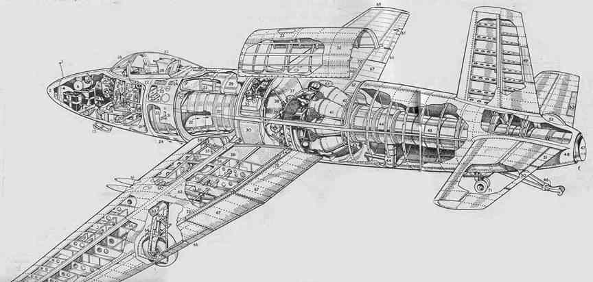
SEA
ATTACKER CUTAWAY KEY
1, Flight attitude sighting bead; 2, Detachable
nose cap; 3, Fixed ballast weight; 4, Armour plate forms forward bulkhead; 5, Batteries; 6, Oxygen
bottle; 7, Lighting for auto-observer panel; 8, Adjustable ballast weights;
9, Power unit for radio (radio, when fitted, is mounted by the side of the
power unit, above the bottom access door); 10, Auto-observer Instrument panel;
I" Engine starter panel; 12, Silica gel bottle; 13, Radio access door;
14, Rudder pedals; 15, Pilot's instrument panels; 16, Engine controls; 17,
Compass; 18, Control column; 19, Flap control; 20, Air bottle; 21, Boundary
layer air Intake; 22, Main air Intake; 23, Boundary loyer
airflow guide channels; 24, Boundary layer aIr outlet;
25, Pilot's foot step; 26, Bullet-proof windscreen; 27, Double-walled sliding
hood; 28, Martin Baker ejector seat; 29, Top main fuel tank; 30, Port side
tanks; 31, Retractable foot step; 32, Engine cover (removed); 33, Extra air
Intake (for ground running); 34, Plenum bay pneumatic seal; 35.. Hydraulic
header tank; 36, Auxiliary gear box; 37, Engine end of air intake; 38, Auxiliary
gear-box drive; 39, Engine diagonal bracing strut; 40, Engine starter; 41,
Rolls-Royce.Nene engine; 42, Fire-extinguisher ring;
43, Bearing cooling air outlet; 44, Jet pipe volute bleed; 45, Removable Jet
tail pipe; 46, Deck arrester hook (down); 47, End of tail jet pipe with 10.
forward rake on top lip; 48, Detachable tail cone; 49, Rudder trim tab; 50,
Elevator trim tabs; 51, Elevator spring tab (port only); 52, Tall parachute
housing (test equipment only); 53, Main wing spar; 54,' Rear spar attachment;
55, Undercarriage fairing door; 56, Hydraulic jack actuating undercarriage
fairing door; 57, Undercarriage operating jack; 58, Port wing fuel tank; 59,
Ammunition boxes built into wing structure; 60, Undercarriage plntle; 61, Hispano 20'mm. gun, Mk. V;62, Gun bay access panels;
63, Dive recovery flaps; 64, Undercarriage leg fairings; 65, Shock absorber
leg; 66, Aileron spring tabs; 67, Trailing edge flaps; 68, Electrically-operated
trimmer tab (starboard only); 69, Navigation lights; 70, Pressure head; 71,
Steerable tall wheel; 72, Wing 11ft spoilers; 73,
Knockout escape panel (each side of cockpit).
![]()
| disclaimer | |
|
page modified |
|
|