|
The Unofficial Yamaha CV80 Owner's Guide
Articles
All Wired UpIf you're crazy enough, you can take apart the wiring on your CV80 and see for yourself most of how and why it works. But you don't have to go that far to learn as much as you should know, not the least of which is that Yamaha was rather sloppy with documentation of its own electrics. Look at a schematic and compare it to an actual CV80 wiring harness: depending on the source of the schematic (eg, owner's manual or service manual) you could find a wire marked "Br" that does not branch to the CDI and ignition control unit as indicated (it should be B/R—a small typo, perhaps, but still important). Similarly, an arrangement of wires in an 8-pin connector to the main switch does not include a wire referred to as "B/r" (it should be B/Y). Legends to the wiring on the CV80 invariably omit one or more colours. Y/W is inexplicably missing in the legend accompanying the schematic in my service manual, for example. Another source faithfully omits Y/W and, for good measure, any mention of red wires on my scoot. Yet for all my craziness in taking apart the wiring I know there is a yellow wire with white marking on it (Y/W) that branches from the lighting circuit to a regulator. And red—well, it's hard to miss (unless you write manuals for Yamaha, I suppose). So wiring a CV80 is as much a task for an amateur sleuth as it is for the ambitious scooter mechanic. Either way, errors are found. The facts are set straight. To start with, Yamaha's engineers used 21 colours in its wiring scheme for the CV80. That included 0.5/20-gauge wire used for most of the 6-volt system and (I'm guessing—it's not labelled) 5.0/10-gauge wire for the battery, starter motor, and negative ground wire. Here's a legend for the wiring harness on my scoot:
And here's an illustration of how wiring is actually assembled on a CV80J:  Never mind the north-south separation of wires in the illustration. What's important is that everything starts at the coupler to the magneto. From there is goes up about 6-8 inches and then to the right and/or left about 36 inches (some wires, such as W/B and L/W, run a full 72 inches or so from the 8-pin or 12-pin connector to a particular unit). Here's a photograph that might help you to visualise how the illustration matches the actual harness. It shows left of the split above the connection to the magneto. 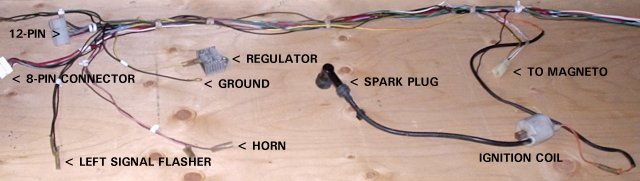 Wires for the fuel and oil gauges branch roughly halfway along to the right. Everything is bundled like thick rope until reaching various connectors. I removed the tape around my harness so I could examine individual wires. Wires do not enter the connectors as illustrated above—more on that later. Remember, too, that the rectangles in the illustration denote connectors and not specific units, such as the CDI or ignition control unit. Arrows indicate bullet connectors, usually shielded. Diamonds are spade or other connectors that a service manual or the wiring on your own scoot will reveal specifically. Dots indicate points where wires are soldered. You can see the main circuits in the illustration. B/R runs from the source coil in the magneto to the CDI and ICU in one direction and off in another to the front of the scoot where it connects to the main switch and kill switch; W/R connects the pulser coil; W is the charging circuit (see the rectifier); and Y/R serves the main lighting circuit, which is regulated. Two wires at the 12-pin connector warrant special mention. Y/R connects to L in a top harness to power the headlight and switching. And R connects to Br to provide power to various signalling circuits (gauges, flashers, etc). The top harness runs 12-14 inches. Here's what it looks like.  Here's how wires actually fit into the various connectors:  There isn't much to it, really—except so far I have yet to figure out the purpose of two wires that connect from the main switch to the ignition control unit (ICU). B/Y is live when the switch is set to START; and W/B is live when the switch is set to RUN. Why, I don't know. Here's what happens at the main switch:  With the key turned to LOCK or OFF, the scooter won't start. When the key is turned to the CHECK position (marked with an asterisk on the main switch), power goes through R to GY to activate the oil gauge long enough for a quick reading via a light on the instrument panel. When the key is turned to START, power via B/Y illuminates an indicator light on the instrument panel (it also runs to the starter relay). The rest of the story will be helped by another illustration: 
But before the engine's RPM increase to the point where the clutch would engage, power via W/R triggers a zener diode that opens SCR2 in the ICU and power is diverted to ground. As RPM fall, SCR2 closes and power is routed to the CDI again—and so on, so that engine RPM are managed to just above idle. The system is designed to prevent the operator from revving the engine while the main switch is set to START. According to my service manual, the ICU does not operate when the key is turned to RUN. As a result, power goes directly to the CDI and the engine will respond to throttle control.
I suspect that the scooter doesn't really need an ICU, so anyone who might be thinking about rewiring a CV80 could probably leave out the circuit—in which case I would expect that the scoot could be started and operated with the main switch set to either START or RUN. Still, I loathe the kind of unsolved mystery that's posed by B/Y and W/B wires going to the ICU. New wiring also presents an opportunity to improve on the original colour scheme used for various circuits. I would prefer a harness using wires coloured to more logically reflect the circuits to which they belong. Even better, I think, would be a harness that could be replicated using the few basic colours of appropriate gauge wire that are typically available—such as red, green, yellow, white, and black—and marking tape. I'll explore that idea later. In the meantime, here are some images of other components mentioned in this article:  DISCLAIMER
I make no warranty of any kind, either express or implied, including without limitation warranties regarding the accuracy, reliability or completeness of information on this site. Anyone using such information to perform repairs or mechanical work of any kind does so entirely at his or her own risk. In no event will I be liable for any incidental, consequential, or indirect damages.
|
 When the start button is pressed or the kickstarter is kicked, the magneto turns and power goes via B/R to charge the capacitor in the CDI. A pulse from W/R triggers a silicon controlled rectifier (SCR1) in the CDI and the CDI discharges to the ignition coil. If all goes well you should get a spark and the scoot should start.
 What's unclear (to me) is why external power is needed by the ICU, first via B/Y when the main switch is set to START and then via W/B when the switch is set to RUN. My service manual indicates that if the operator attempts to start the scoot with the key in the RUN position, SCR2 is opened (presumably by W/B) and power goes to ground so the scoot won't start. I don't understand how that could happen, but at least it sounds like a plan. So what does B/Y do when the main switch is set to START?