
CONTINUED |
 |

electriCar2 |
 |
(IMAGE NO.08)The image above is a low volume battery swap station. Eventually as the number of EVs increase in volume the demand from each refuel station will increase. The second Image illustrates a higher capacity to minimize any waiting for recharged batteries. As more and more long distance travellers ride the interstate roads similar to highway stations today , the lower Image will will be more the norm as the people finally switch to the EVs and especially those that will interface with my HIGH SPEED GLOBAL MAGLEV SYSTEM mentioned below and in index4.(cont.)
|
![]() |
| (IMAGE NO.09> |
![]() |
| (IMAGE NO.10> |
![]() |
| IMAGE NO.11(cont.) |
----------
| 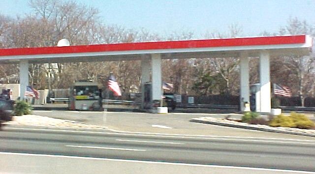 |
| (IMAGE NO.15 Above)Here is a regular gas station on Route 3 in New Jersey before it was changed to accomodate EVs (electric vehicles)
|
|
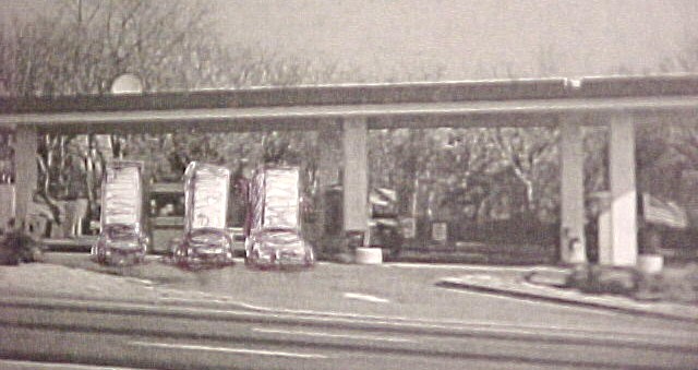 |
| (IMAGE NO.20 Above)This is the same station as in Image 15 above but the gas pump island on the left was removed and replaced with three battery towers as shown with 3 electric cars swapping batteries while the gas pump island on the right is still refueling the remaining gas fueled autos for a few more years when the remaining islands will also be replaced by battery towers also. |
![]() |
| (IMAGE NO.25> |
 |
(IMAGE NO.31)Above is a typical gas station with 2 gas pump islands requiring attendants and maintenance crews for servicing
the various complexities that goes with the gas engines and hybrid cars. Today 2002 Nothing much has changed to
protect the planet and also reduce the use of combustible fuels refined from oil. A depleting source which should best be preserved for many more years for other purposes such as lubricants ,polymers ,plastics, etc. In other words what's in the ground is "money in the Bank" where the price per barrel 50 years from now, used for other applications could be worth today's prices tenfold then.(cont)
|
 |
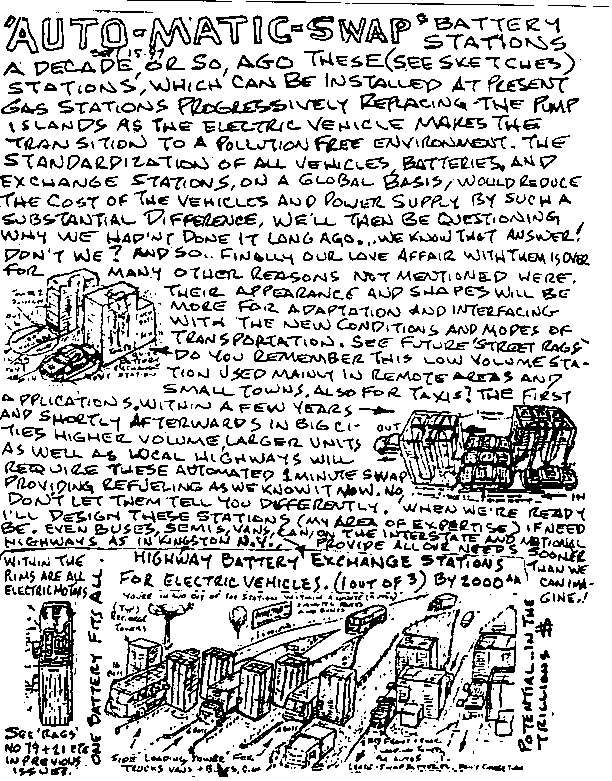
(IMAGE NO.35)--It's now year 2006 and were moving to the change over to simpler and safer vehicles.In image 4 way above is a
previous Street Rag sketch showing a low volume E.V. battery exchange and recharge station using a standardized concept battery as shown is applied in Image 8f just above and in 8g just below. (One size, one voltage.The content or range are irrelevent,the customer will determine his or her preference.)As you may noticed in these two images one island has been removed and replaced by 3 low volume battery exchange
towers.This top view shows 3 EVs at each tower in progress of swapping batteries.Behind the towers is the battery company truck which once a month or whenever its called for comes to the station to replenish the reserve 3rd stack with brand new ones while taking the old and no longer rechargeable ones back to the factory to be reprocessed using the salvageable materials to make new ones.That truck is automatically positioned to interface with the rear of the towers to make that exchange also.Like the buses and semis in page 3b,click at bottomthis truck can be positioned by an indexer alingning the battery replenishment.Image 8g below shows a pictorial view of EV batteries in progress of being swapped.(cont)
|
 |
(IMAGE NO.39>These towers above,left,which permit the batteries to flow through them while being recharged are relatively
simpler and smaller than those shown above for highway stations including vans and semis side loading methods
also.(see index3a.html) In the perspective view above the EV car driver inserts a credit card or cash into a collector,
then drives onto a turntable, butts against the tower ,the front battery is extracted to the 2nd stack at the rear and
which once checked for possible rechargeability and remaining energy which is credited to user. (another way to
pay for the energy is to bill customers monthly for mileage driven -- to be elaborated on later)the battery is then
simultaneously raised one level while the front stack is lowered proportionately,then permitting also a transfer at
the top of the stack from rear to front as well as a new insertion at the bottom into the front of the vehicle. The
car is then rotated 180 degrees and the same extraction and insertion is repeated in the rear. Then the vehicle
drives off for another 500 mile range where within a minute the sequence is repeated then at the next swap station
and so on and on.A 'solectria EV' car using nickle metal hydride batteries occuping no more space than one of these
batteries went from Boston to New York on one charge which equals about 250 miles.Note: The third stack shown in
the sketch above is for batteries no longer rechargeable.Every battery is tested for that purpose at the start of the
recharging process. If rejected it is transferred to the 3rd'service' stack at the far rear as shown above and when
,progressively, the vacant 'slot' in the 2nd stack reaches the level of the top of the 3rd, a new battery is inserted
in theempty spot. As required a service truck with brand new batteries replenish the third stack with new ones and
return the the old ones to the factory to be totally recycled.I.E. slice them open, reove the ingredients and reprocess
them to for manufacturing new ones ,thus reducing the cost of materials and conserving the planets resources in the
process. (cont.)
|
 |
(IMAGE NO.44)Here also on 34th st. Manhattan is a Mobil gas station today. In a few years from now see below. |
 |
(IMAGE NO.51)The gas pumps were replaced with battery exchange stations first used by taxis and then private EV owners. |
 . .
|
(IMAGE NO.52)Here is TOYOTA futuristic car with front and rear cavities...??? You guessed it.!!! For swap batteries..maybe? . cont) |
 |
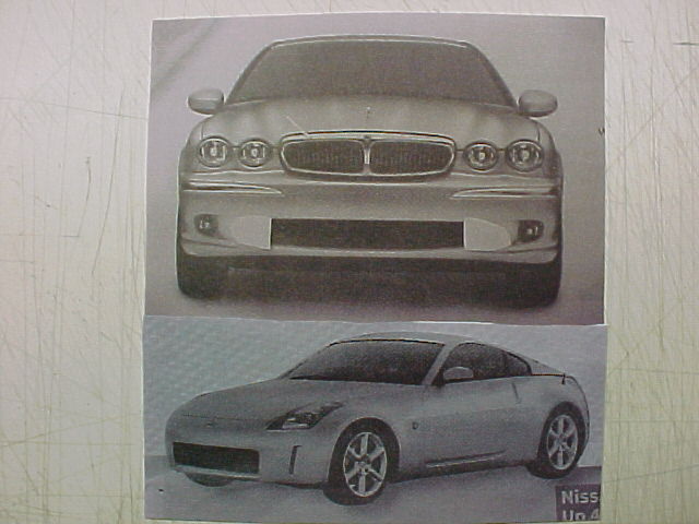 |
IMAGE NO.54 Above is a top view of a Jaguar with 2 removable batteries front and rear. Just below is the front view of that same Jaguar and just beneath it is a Nissan. Both have a substantial opening in the lower front end, and if one's guess is correct they will all be used in the future for the insertion of electric batteries. The same holds true just below.(cont.) |
 . .
|
(IMAGE NO.57) The Honda on the left and the Cadillac with the "BREAK-THRU" hole on the right are also getting ready. Let's not kid ourselves, why would they copy each others design if they were not planning for the one size and voltage battery swap concept. cont) |
![]() |
(IMAGE NO.60(cont) |
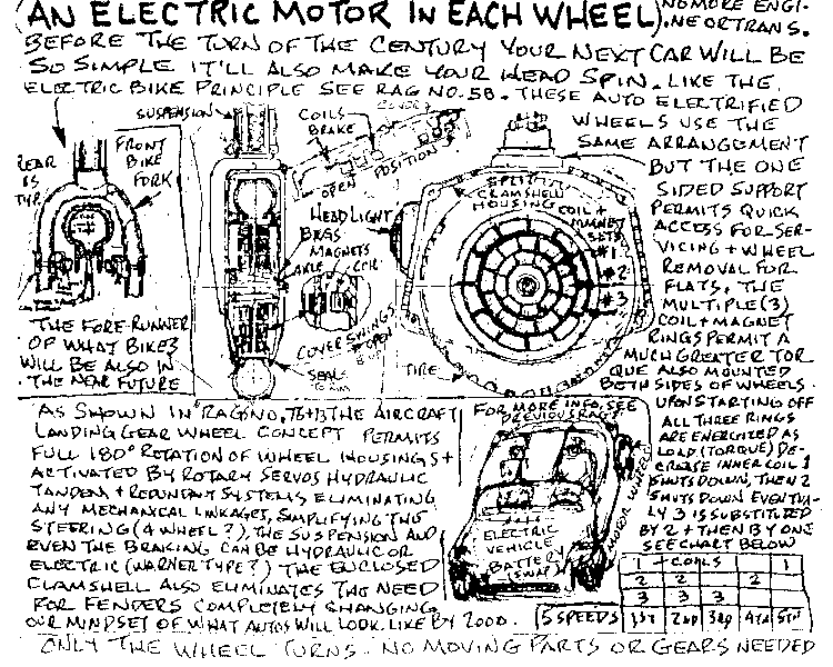 |
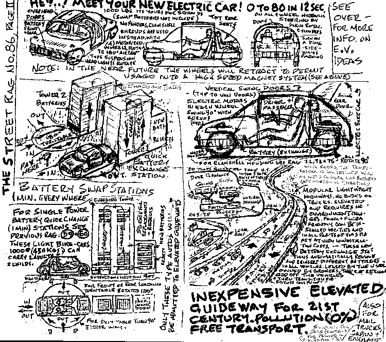
IMAGE NO.63 Many of the features in this page originated in the 90s and previously shown in the STREET RAG (my publication)are controlled electrically and/or hydraulically rather direct mechanical connections and what GMC now calls BY-WIRE Which will be applied to their SKATE-BOARD having a removable passenger capsule which is also an idea I suggested then for insertion in the HIGH SPEED MAGLEV SYSTEM. (see BI-MODAL MODULE at the bottom of this page and in index4).The above shows the electric motor in each wheel. only the hub and tire rotate on all four wheels.The sketch at left is a retake of 'rag no.58'It's a cross-section of a motor and generator concept on a previous idea for an electric bike.The electric vehicle wheel shown here is somewhat of the same principle and all four are identicle. But it is airtight with dirt seals and has a hinged front cover facing outward which can be opened to replace,if ever need be, one of the six coils (3 on each side)or to repair a flat tire or replace it. Like an aircraft wheel the axle is mounted from one side and the turning axis and suspension is dead center above the wheel.This could then permit with electronic controls and dual(as a fail safe redundant system)controls as applied to aircrafts etc.. With such a system we could then program all types of possibilities such as in a stopped mode,turn all wheels 90 degrees sideways and with a programmed low speed 'crawl'mode the car sideways into even a tight parking spot. In your back yard you'd command a theoretical pivot axis point upon which all wheels become perpendicular to it and depending which way you want to turn 2 on one side propel forward while the others backwards and thus in a very small space the car turns on itself ready to leave your driveway.Just command a different pivot point you could still turn in small spaces.The possibilities are quite numerous.Depending how we provide power to the wheels could provide us with various torque ranges even without varying the voltage. The chart at bottom right gives us an idea of how it can work.here it gives 5 'speeds' with no gears needed. (cont)xxxxxxxxxxxOne possibility to minimize energy consumption is to control the torque of the motor without energy loss or heat loss.By using three coils small,medium,and large in each wheel,five different torque ranges are available. The firstspeed, by energizing all three coils gives the maximum torque required for start off,then as less power is needed the computer shuts off the first,or smallest coil with only the two outer ones energized, as acceleration increases and less torque is needed again the second ,or intermediate one shuts off leaving only the outer one activated. that's the third speed and as acceleration increases again that third one ,the outer, shuts down as the intermediate only takes over and finnally again only the smallest or the fifth speed is the high gear engaging all four wheels coasting at higher speeds.
Should more power be required for upper inclines or acceleration automatically the process and sequence reverses itself.
The following are some existing patents of other "in-wheel EV motors". Click on them.
|
5691584
(cont)
CONTINUE
P.S.---MY SERVER --'GEOCITIES'-- SENT ME THE FOLLOWING"--Your site has become so popular,in fact,that our records indicate that you're using more than the allotted amount of data transfer we provide and it could be disabled until usage falls to within the prescribed limits.."---AS AN ALTERNATIVE...
If at times you cannot access or continue in these web pages, many more are also duplicated in the (TOPCITIES)'html'pages.
then click here meanwhile
##
|
|