| Rear Suspension | ||
| DIY DeDion !! |
Hopefully it will look something like this ..... |
|
| . | . | Believed to be MK Engineering DeDion setup |

Design Brief | ||
| . | I really wanted to have the wider chassis
( to give more room for me and engines/gearboxes etc.)
but this meant that I couldn't use the standard rear axle.
The only wider Ford live axle was the Cortina lump, but I
Australia this is a Borg Warner part that weighs four
times the Escort axle. This would have to have a
significantly detrimental effect on the handling of a car
this weight, especially on Australian roads. I looked at
a huge number of Japanese axles (many weekends spent
crawling under cars measuring rear axles at your friendly
wreckers!) and found a few that would do but this then
added the problem of different PCDs between front and
back axles. Also, I didn't really want to use drums on the
back so the only real option became a Mitsubitsi Scorpion
live rear axle which was still going to be a bit tight in
the wider chassis. All this time the IRS bug was chewing
at my ear, so I also looked into that. A full unequal length wishbone rear was well beyond my design skills, but at some stage I got the idea to do a DeDion rear. Again after much crawling under wrecked cars with a tape measure I finally found a donor I thought I could modify into a DD rear setup. The donor was a 1982 Nissan Skyline Hatch with an IRS using semi-trailing arms. I figured that I could chop the semi-training arms off the wheel hubs and weld on a bracket for the DD axle to attach to. After that it is simply a matter of using the four trailing arms and panhard rod design from "The Book", with a few minor adjustments. I'm yet to see if its that simple ! |
|
Construction |
||
| . | The latest plan is to use part of the existing semi trailing arms as the attachment point for the deDion bar. (if this doesn't work we can go back to making a separate bracket) By cutting off most of the semi trailing arms (leaving about 10%left on) and swapping the hubs left to right, this left the 'stubs' pointing backwards ready for a tube to be welded between them. By constructing a suitable jig to hold everything in place during the welding, I thought that this wasn't beyond my capabilities. The semi trailing arms actually point downwards slightly, but this can be compensated for by bending the deDion tube appropriately. | |

 |
Cutting the Semi Trailing Arms off The first thing to do was to cut the hub assembly from the Semi trailing arm. A cutting wheel on a grinder was used. |
|

 |
Making the Jigs Version 2 of the deDion jig used 2 separate jigs which will be held in another jig. the relationship between the jigs will establish the track and camber. The hubs are set with a measured toe in already setup. (The hub assembly is held so that the deDion bar will be on attached at the top) |
|


 |
Sculpting the Hubs The hubs were sculpted so that the deDion bar would rest at the correct angle and allow a suitable area for them to be welded together. |
|
| Mark II Design | After welding on the tube brackets etc, everything looked Great until we fitted the Brake calipers and found that the handbrake activator arms hit the chassis. After much swearing and messing around we had to accept that the initial design wouldn't work and we had to go to our Mark II design. The new design involves removing all the old semi trailing arms and fabricating a new deDion 'ear' which connects the hub and tube. The ear will be bolted to the hub and welded to the tube. We have now rotated the hub assembly so that the brake caliper is on the top and clear of all chassis parts !! All the same jigs are used. |
|


|
New Dedion design showing the dedion ear and fitting. | |

|
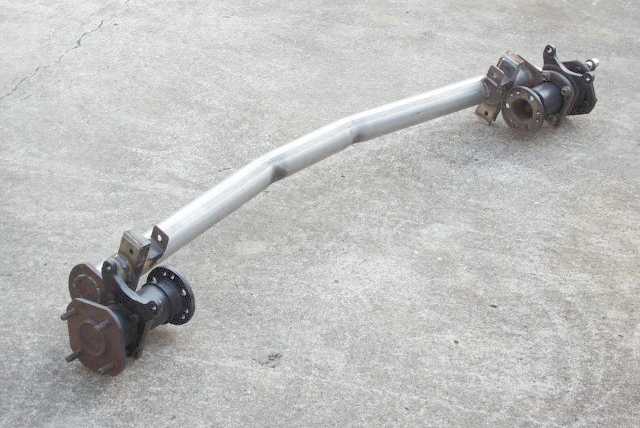
The finished article The DeDion axle is now largely finished and the car rolls. I still need to finalise the Panhard bracket but that wont be difficult. The end result appears to work well and clear everything well. The DeDion axle and diff are are quite compact so a good sized boot should now also be possible. |
|