(Warning: Many Pictures)


| Walking Robot Progress Gallery (Warning: Many Pictures) |
||||||||||||||||||||||||||||||||||||||||||||||||||||||||||||||||||||||||||||||||||||||
|
|
|||||||||||||||||||||||||||||||||||||||||||||||||||||||||||||||||||||||||||||||||||||
| These are some pictures genorated by a 3-D modeling program, Solid Edge. Incredibly easy to use, it lets you draw things on the computer in 3-dimentions with control over every aspect of the drawing and part location process. See Robot Model for an explaination of the parts. | ||||||||||||||||||||||||||||||||||||||||||||||||||||||||||||||||||||||||||||||||||||||
|
||||||||||||||||||||||||||||||||||||||||||||||||||||||||||||||||||||||||||||||||||||||
|
||||||||||||||||||||||||||||||||||||||||||||||||||||||||||||||||||||||||||||||||||||||
| This is a recent sketch I made of how I wanted the legs to be positioned. This sketch came out of my design notebook that is about 95 pages thick right now. | ||||||||||||||||||||||||||||||||||||||||||||||||||||||||||||||||||||||||||||||||||||||
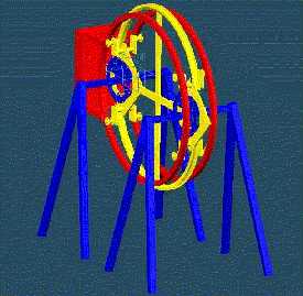
| Here is the construction as of 12/09/99. the basic framework is shown with the newly mounted pendelum swing rings. | ||||||||||||||||||||||||||||||||||||||||||||||||||||||||||||||||||||||||||||||||||||||
| To the left is a general setup of how I want the legs to be positioned (notice the wooden leg used in place of a two tirpod legs that I have yet to aquire). 12/10/99 | ||||||||||||||||||||||||||||||||||||||||||||||||||||||||||||||||||||||||||||||||||||||
| To the right is the improved leg attachment to the hip joints. The position that it is in is not an opperating position for the robot. 12/20/99 | ||||||||||||||||||||||||||||||||||||||||||||||||||||||||||||||||||||||||||||||||||||||
|
||||||||||||||||||||||||||||||||||||||||||||||||||||||||||||||||||||||||||||||||||||||
|
||||||||||||||||||||||||||||||||||||||||||||||||||||||||||||||||||||||||||||||||||||||
|
||||||||||||||||||||||||||||||||||||||||||||||||||||||||||||||||||||||||||||||||||||||
| These two pictures were taken recently (01/07/00). They show the mounting of the chain guide ring that will allow the pendelum to lock into its post swing positions via a chain sprocket located onboard the pendelum. | |
|||||||||||||||||||||||||||||||||||||||||||||||||||||||||||||||||||||||||||||||||||||
|
||||||||||||||||||||||||||||||||||||||||||||||||||||||||||||||||||||||||||||||||||||||
| My beautiful work area. On the table is a new Black and Decker cordless screwdrive that I got for Christmas from my sister. Using it, I found that it has the torque, and unpowered-shaft-locking characteristics that I need for my robot. I plan on buying another of these to drive the overhead swing, and pendelum make-up swing functions of the robot. (01/07/00) | ||||||||||||||||||||||||||||||||||||||||||||||||||||||||||||||||||||||||||||||||||||||
|
||||||||||||||||||||||||||||||||||||||||||||||||||||||||||||||||||||||||||||||||||||||
| Me and my robot posing for a picture taken by one of my mechanical engineering professors -Dr. Bob Williams. This was just after I gave a 15 min presentation on why the robot represents a good design solution, how it works, and the results of my dynamic analysis. Notice the wooden leg it has now -until I get some more tripods for it. (02/03/00) | ||||||||||||||||||||||||||||||||||||||||||||||||||||||||||||||||||||||||||||||||||||||
|
||||||||||||||||||||||||||||||||||||||||||||||||||||||||||||||||||||||||||||||||||||||
| The robot and how it would climb up steps if it had motors and such things (a dream right now). This picture was again taken by Dr. Bob Williams. (02/03/00) | ||||||||||||||||||||||||||||||||||||||||||||||||||||||||||||||||||||||||||||||||||||||
|
||||||||||||||||||||||||||||||||||||||||||||||||||||||||||||||||||||||||||||||||||||||
|
||||||||||||||||||||||||||||||||||||||||||||||||||||||||||||||||||||||||||||||||||||||
| The new legs of the robot as of 03/04/00. These would latter prove to be to flimsy to support the latteral loads resulting from the pendelum swing. | ||||||||||||||||||||||||||||||||||||||||||||||||||||||||||||||||||||||||||||||||||||||
|
||||||||||||||||||||||||||||||||||||||||||||||||||||||||||||||||||||||||||||||||||||||
|
||||||||||||||||||||||||||||||||||||||||||||||||||||||||||||||||||||||||||||||||||||||
| These pictures show the loaded body of the robot. The loads on the frame are to simulate the opperational weight of the pendelum that must counterballance the weight of the remaining robot body and the weight of motors and other control parts. | ||||||||||||||||||||||||||||||||||||||||||||||||||||||||||||||||||||||||||||||||||||||
|
||||||||||||||||||||||||||||||||||||||||||||||||||||||||||||||||||||||||||||||||||||||
| Upon loading the robot. I cut the rope simulating the release of the pendelum weight. The robot promptly fell on its face, defying the dynamic analysis I had done, and making me a bit doubtful of my skills in modeling physical events. | ||||||||||||||||||||||||||||||||||||||||||||||||||||||||||||||||||||||||||||||||||||||
|
||||||||||||||||||||||||||||||||||||||||||||||||||||||||||||||||||||||||||||||||||||||
|
||||||||||||||||||||||||||||||||||||||||||||||||||||||||||||||||||||||||||||||||||||||
|
||||||||||||||||||||||||||||||||||||||||||||||||||||||||||||||||||||||||||||||||||||||
| After being angry and a bit humored at my own foley, I investigated the problem. I found that the legs had bent under the loading. This caused the resistive moment arm of the weight of the robot to shorten, allowing the whole robot to circum to the opposing torsonal moment and so tipping the robot over. | ||||||||||||||||||||||||||||||||||||||||||||||||||||||||||||||||||||||||||||||||||||||
|
||||||||||||||||||||||||||||||||||||||||||||||||||||||||||||||||||||||||||||||||||||||
| I artificially braced the feet of the robot due to the lack of any other stronger building materials. Since the legs of the robot are meant to be stationary and solid durring the swing phase of the robot's movement, all the duck tape sturdies up the legs of the robot. The result was a successful test that illustrated that my orrigional dynamic analysis was correct. I intend on changing the pendelum weight so that it rotates like a flywheel. This would slow down the pendelum motion so that the risk of a tip over would be less likely | ||||||||||||||||||||||||||||||||||||||||||||||||||||||||||||||||||||||||||||||||||||||
| Recent Design Changes to both legs, main body, pendulum, and pendulum rotation rings. (09/10/00) | ||||||||||||||||||||||||||||||||||||||||||||||||||||||||||||||||||||||||||||||||||||||
|
||||||||||||||||||||||||||||||||||||||||||||||||||||||||||||||||||||||||||||||||||||||
|
||||||||||||||||||||||||||||||||||||||||||||||||||||||||||||||||||||||||||||||||||||||
|
||||||||||||||||||||||||||||||||||||||||||||||||||||||||||||||||||||||||||||||||||||||
|
||||||||||||||||||||||||||||||||||||||||||||||||||||||||||||||||||||||||||||||||||||||
| Since the dead pendulum exerted dangerously high forces onto the main body of the robot, I altered the movement nature of the pendulum so that it acts as a flywheel. The flywheel onboard the pendulum will be driven off of its own weight, as it rotates about the stationary circular track attached to the main body. Above are some pictures of the 3-4 week construction job it took to asemble the flywheels using the iron core windings of two old overhead ceiling fan motors. | ||||||||||||||||||||||||||||||||||||||||||||||||||||||||||||||||||||||||||||||||||||||
|
||||||||||||||||||||||||||||||||||||||||||||||||||||||||||||||||||||||||||||||||||||||
|
||||||||||||||||||||||||||||||||||||||||||||||||||||||||||||||||||||||||||||||||||||||
|
||||||||||||||||||||||||||||||||||||||||||||||||||||||||||||||||||||||||||||||||||||||
|
||||||||||||||||||||||||||||||||||||||||||||||||||||||||||||||||||||||||||||||||||||||
| The flywheel was then attched to a complex tensioning mechanism shown above. The purpose of this mechanism is to allow the free, external rotation of the pendulum cart about the main body, and to keep tension on the chain. The two main chains that surround the main body, laying in the grooves of the two pendulum rings, drive the pendulum's flywheel as the pendulum swings from one side of the robot to the other. The end result is a more stable pendulum swing phase of the robot's movement. | ||||||||||||||||||||||||||||||||||||||||||||||||||||||||||||||||||||||||||||||||||||||
|
||||||||||||||||||||||||||||||||||||||||||||||||||||||||||||||||||||||||||||||||||||||
| Here is a picture of the final (or mostly final) assembly of the main body with the new legs.(09/11/00). | ||||||||||||||||||||||||||||||||||||||||||||||||||||||||||||||||||||||||||||||||||||||
|
||||||||||||||||||||||||||||||||||||||||||||||||||||||||||||||||||||||||||||||||||||||
| Further work on this project (like the addition of motors and the implementation of my electrical schematic) is postponed untill I get some time and some money in my life. The project so far has cost me around $700. | ||||||||||||||||||||||||||||||||||||||||||||||||||||||||||||||||||||||||||||||||||||||
| Back to robot page | ||||||||||||||||||||||||||||||||||||||||||||||||||||||||||||||||||||||||||||||||||||||