
If you want to ask me any questions, you can reach me at pocher_rolls@yahoo.com.
Next was the spark plug wiring. Here, I had done some research on actual Rolls Royce Phantom II engines and I made my first modification. The instructions indicate that on the intake side of the cylinder head, three of the spark plug wires for the primary ignition system go directly from the distributor to the plugs and three go through the spark plug wire tube to the other three plugs (this next photo was scanned off the box).
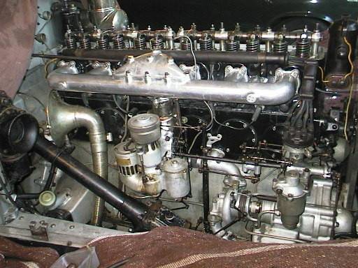
Roll Royce did it differently (and more elegantly too). They had a separate hole in the spark plug wire tube for the first 5 wires and the sixth came out the end of the tube to the sixth plug. The next two photos were the only ones I could find on the web. Some books in libraries and bookstores had more photos. You can see the spark plug wires coming down from the tube for the first two spark plugs in the first photo, a little more in the second photo, not to mention the more similar carburetor and intake assembly seen in the second photo (both are from the Rolls Royce owners club of Australia web site). By the way, I don't think that the chrome plated valve cover was original although it does look cool. Also note the open valve on the third cylinder from the front in the second photo.

I got some long brass tubing that was the same diameter as the tube supplied by Pocher, cut it to an adequate length and drilled 5 holes. That was the easy part. Next was threading the wires through the tube and the little holes. Don't try this unless you have LOTS of patience. The first four wires weren't bad at all, the fifth one wasn't too bad, but the sixth wire was REALLY snug. I started with the first cylinder (the one closest to the distributor) and worked my way back. Well, the hard work paid off with a very tidy assembly that, in my opinion, looks sharper than what the instructions called for, painting the white porcelain insulators of the sparks helps to accent them as well. The clips that attach the tube to the head are flat off the tree and you have to bend them into shape so they wrap around the tube and allow the tube to sit between the valve cover and intake manifold (later). It was at this point in the assembly where my heart skipped it's first of many beats. The screw that attached the water pump assembly sheared the head off as I tightened it. Well, that had to be drilled out, the hole cleaned up, filled and re-drilled for another screw. Fortunately, a model shop in my area has adequate screws.

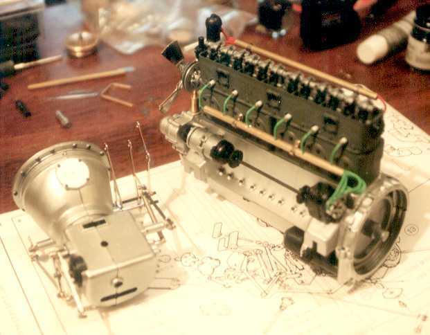
The wires on the exhaust side for the secondary ignition were another story. At the time I assembled that part of the engine, I couldn't find any photos of the exhaust side of the Rolls Royce Phantom II engines. However, common sense and mechanical intuition led me to think that Rolls Royce would have engineered something similar on that side as they did on the intake side. After all, you certainly wouldn't want to run the risk of your spark plug wires coming in contact with the hot exhaust manifold. With that in mind, I made another tube identical to the one on the intake side and I made two more mounting brackets from scratch. Fortunately, there were already two fittings on the side of the blocks where this other tube and brackets could be mounted (how convenient). I completed this part of the assembly in late-March and by early May, I found this photo, also on the Rolls Royce owners club of Australia web site. It turns out that I made the tube with one too many holes, oh well, if you want to try this, it should be much easier for you than it was for me. At this point, the dynamo and magneto were also installed. I think the spark plug wires look much more orderly than what the instructions indicate. Again, the real challenge was threading the wires. Here you can also more clearly see the three looped ends of the transmission linkages where the pedals would later be attached (to the right of the bell housing just above the upper edge of instruction book). Those loops would each need to be bent (rotated) by 90°.

The intake assembly was the next place where I sheared the head off a screw. After I sheared the head off this screw, I started to get a feel for how much torque I could put on a screw before the head would shear off. From that point on, I test fit each and every screw and for those screws that seemed to fit too tight, I drilled out the hole a little. No more sheared screws. This is also where I had to adjust (that is bend) the clips that hold the spark plug wire tube so that the manifold would sit right and the valve cover could be removed. The manifold was also slightly warped which in itself isn't so bad but combined with the warp of the head, it was another few hours of adjusting to get the proper fit. I also noticed that where was some kind of fitting on the rear block on the intake side close to the cylinder head surface. I didn't know it at the time but this was for the oil cooler lines (later).

Yet more research revealed that oil cooler lines needed to be installed on the engine based on the photos on the box and the instructions. The basic information part of the instructions mention that there are oil cooler lines that need to be cut to length but nowhere in the assembly itself do they show the oil cooler lines except for a drawing of an assembly where they are magically in place. Also, the photos on the box show the lines as well. Interestingly enough, the photos I've seen of the original engine didn't show those lines, let alone where they were supposed to go.

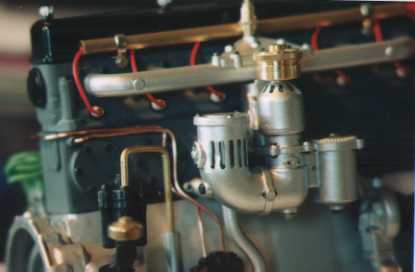
From this angle, you can see where one of the cooler lines attaches onto the block and runs down to the oil pan. Again, common sense and mechanical intuition leads one to the conclusion that where there is one cooler line, there must be a second (one for incoming and one for outgoing). You can also see that the grille on the air intake for the carburetor looks damaged. It was actually worse when I started that assembly. I may go back later and try to repair it further.
The second line was supposed to go to one of the fittings where I attached the secondary spark plug wire tube (oops). So, I had to make a new fitting. I used a piece of the tree to manufacture the fitting and I attached it to the opposite corner of the first fitting. This actually looks more elegant and seems more mechanically correct as cooling technology goes. Plus, these modifications have the added benefit of utilizing all the fittings on the engine leaving nothing looking as though it were unfinished.
The next thing was the fan belt, probably the easiest assembly in the entire project.

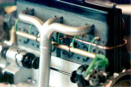
Another view of the intake side of the engine showing the close tolerance of the intake manifold to the tube to the valve cover.
