
SeGuruCool
The Largest Independant Solid Edge Resource Outside UGS

SeGuruCool The Largest Independant Solid Edge Resource Outside UGS |
|
www.oocities.org/SeGuruCool  segurucool @ indiatimes.com segurucool @ indiatimes.com |
|
|
|
In this tutorial you learn : It is assumed that you are familiar with the basics of Solid Edge Part modeling. | 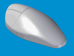 |
|
Visualize First From front, the mouse would look something as shown in figure. | 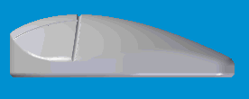 |
|
Sketch It So, in the x-z plane, sketch a spline as shown. | 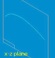 |
|
Visualize Again From left, its like this. |  |
|
Sketch the Other View In the y-z plane, sketch a spline as shown. | 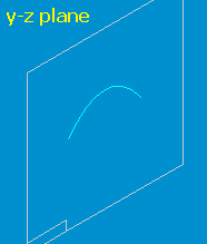 |
|
Prepare for BlueDot Click the BlueDot  tool from the Surfacing toolbar. tool from the Surfacing toolbar. Click the two splines one after the other. |  |
|
Tie the Splines Click Finish on the ribbon bar. The two splines get tied with a bluedot at their intersection. | 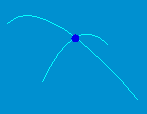 |
|
Create the BlueSurf Click the BlueSurf  tool from the Surfacing toolbar. tool from the Surfacing toolbar. Select one of the splines. Click accept  on the ribbon bar. on the ribbon bar. Then select the other spline. Click Finish on the ribbon bar. A bluesurf is created as shown in figure. | 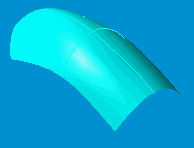 |
|
Create the Body Profile The bluesurf created in last step is the top surface of the mouse that would fit into your palm. Hide the bluesurf for now. To create the body of the mouse, draw a profile in the x-y plane as shown. | 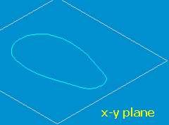 |
|
Create the Body Extrude the profile as shown to an arbritrary height. This can be changed later to suit. |  |
|
Display the Surface Display the previously hidden bluesurf. | 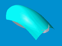 |
|
Select Face to Replace Click the Replace face  tool from the Surfacing toolbar. tool from the Surfacing toolbar. Select the top face of the protrusion. Click accept  on the ribbon bar. on the ribbon bar. |  |
|
The Replacing Face Then select the bluesurf as the replacing face. Click Finish on the ribbon bar. | 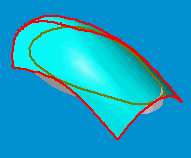 |
|
Face is Replaced The top flat face of the mouse body is now replaced with the bluesurf. |  |
|
Mouse Buttons To create the mouse button etching, create a parallel plane to the x-y plane. Sketch a spline on it as shown in figure. Click the Project Curve  tool from the Surfacing toolbar. tool from the Surfacing toolbar. Select the spline as the curve to project. Click accept  on the ribbon bar. on the ribbon bar. Select the top face of the mouse body to project the curve onto. Click Finish on the ribbon bar. The spline is projected on the top face of the mouse as shown in figure. |  |
|
Prepare for a Swept Cutout Click the Plane Normal to Curve tool from the Features toolbar. |  |
|
Create a Normal Plane Create a plane at one end of the projected curve as shown. |  |
|
Create the Cross Section Sketch a small circle on the nascent plane. |  |
|
Take a Swept Cutout Create a Swept Cutout  using the circle and the projected curve. using the circle and the projected curve.
|  |
|
Its Not All Over Zoom into the area where the swept cutout starts. The cutout has left some material behind where it started. | 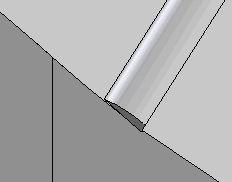 |
|
Rectification Create a normal cutout again using the same sketch (circle) used for the swept cutout. |  |
|
This Looks Better | 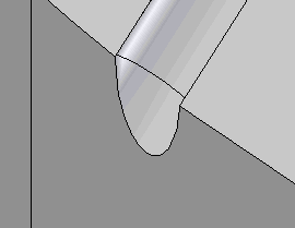 |
|
Same Story on Far Side On the other side, where the swept cutout ends, the case is similar. But there is no sketch (circle) to take the normal cutout and to extend the swept cutout far outside the mouse body. We need to create a curve to take the cut. | 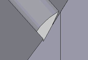 |
|
Derive a Curve Click the Derived Curve  tool from the Surfacing toolbar. tool from the Surfacing toolbar. Select the edge of the swept cutout. Click accept  on the ribbon bar. on the ribbon bar. | 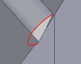 |
|
Curve is Derived The edge is derived as a curve. See figure. Using this curve, take a normal cutout and extend the sweptcut, outside the mouse body. | 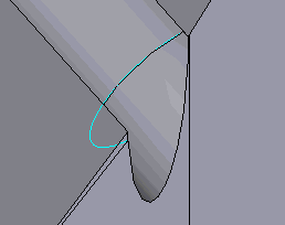 |
|
Make the Buttons Similarly, take two more swept cutouts to make three buttons. |  |
|
Merge the Cutouts Also extend the cutouts for the mouse button seperations where they meet the previous swept cutout. | 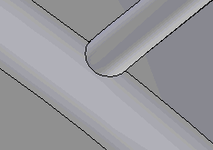 |
|
Aesthetics, etc Round the sharp edges at the base and top to give the mouse more aesthetic looks, etc. |  |
Tushar Suradkar  segurucool @ indiatimes.com segurucool @ indiatimes.com |