Cheers,
Adam Till
In any aircraft, the single most critical structural component is the main wing spar. Yes, that's a big statement to be making, but it's my webpage, so I'm allowed :) Since Aerodesign aircraft end up weighing quite a bit when fully loaded, designing the spar becomes a little tricky. Additionally, since the high-lift wings are capable of generating massive amounts of instantaneous lift in tight maneuvers, the situation becomes even more complicated. Luckily, I'm a sailplane pilot, and I'm used to designing winch-proof spars. Ever try making a 5 lb sailplane capable of surviving a 200lb point-load from a winch? The situation is remarkably similar.

Above Middle: After gluing the carbon laminates to the spruce longerons with cyanoacrylate glue (hereafter known as CA so my fingers don't fall off), the spruce caps are notched to accept the carbon fibre joiner tubes. Even though the spar is made to the full depth of the wing section, the tubes are rather large, and the spruce is really only there to provide a gluing surface for the carbon. The spruce can be planed down for the truely weight-concious, but I didn't see the benefit being worth the added hassle. Since the wing this year will be made in three removable sections, the joiner tubes are added to accept carbon joiner rods. Sensing a pattern here? This airplane is on a high-fibre diet; carbon that is! There will be two spar assemblies built. The center panel has joiner tubes on each end to accept the tip panels, and the spars for the tip panels can be built as a single section and cut apart after curing.
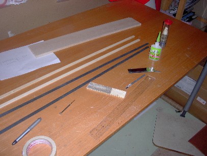
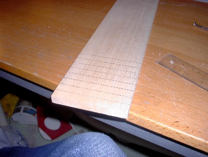
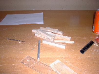
Above Right: While the carbon laminates are more-than-capable of taking the bending loads for the wing, a strong shear web is needed to complete the spar structure. End-grain balsa is used to accomplish this function, since it is light and strong when the grain structure is oriented properly. Here the balsa is being marked for cutting.

Above Middle: The webs are then epoxied to the bottom spruce cap and the taper is finish-sanded. CA doesn't bond well to end-grain balsa, but might be used in a pinch.
Above Right: Here the assembly is dry-fitted to check for overall thickness consistancy. The tube is epoxied to the bottom cap, keeping one face flush with the table. The spar will be bagged staight against a rigid form, so try to keep all the faces of the spar in alignment. DO NOT GLUE ANYTHING TO THE TOP CAP!!! The form will ensure that the spar is straight.


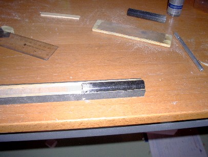
Above Middle: Since the tubes introduce a stress riser into the spar structure, I wrapped the spar ends in Kelvar tape to prevent failure at the interface. The Kevlar is tacked to the carbon cap with CA to allow the wraps to be applied with a bit of tension, then the top cap is glued to the spar with slow-cure epoxy. The ends are wrapped with Kevlar, then the rest of the spar is wrapped with the fibreglass tape. Then the whole mess is then saturated with epoxy, and wrapped in wax paper to prevent the spar from sticking to the vacuum bag.
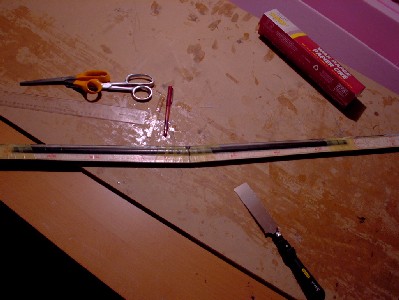
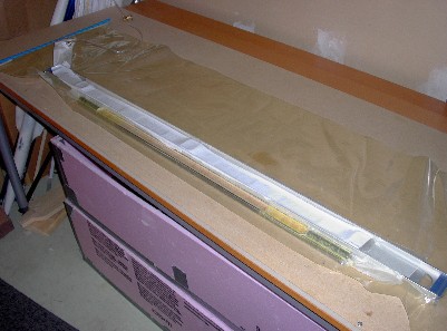
Above Right: Here't the spar in the vacuum bag, which is basically a nylon tube that is sealed at each end, and has a fitting that allows the air inside to be drawn out. I'm using an aluminum I-beam level for a form, and the spar is pulled tight against the level to ensure that it stays straight.

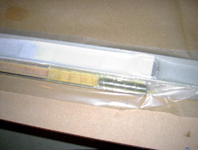

Above Middle: This shows the end of the spar in the bag, and how everything is pressed firmly into place. Trying to squeeze excess resin towards the end of the spar will allow it to be sanded off later.
Above Right: This shows the final step in constuction of the outboard spars: the completed and trimmed assembly is cut in half. Obviously, the center spar is left intact!