The Structure
|
|
| Engine House Terms
The Structure |
|
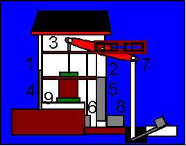
A simple
cross section diagram of a typical Pumping Engine.
In this picture the shaft on the right . Winding and pumping engines would normally have loadings for the flywheel(s) infront of the bob wall. 1 Rear wall 2 Bob wall 3 Wing walls 4 Cylinder Doorway 5 Plug doorway 6 Cockpit 7 Beam 8 Condensor 9 Bedstone |
| Other related terms |