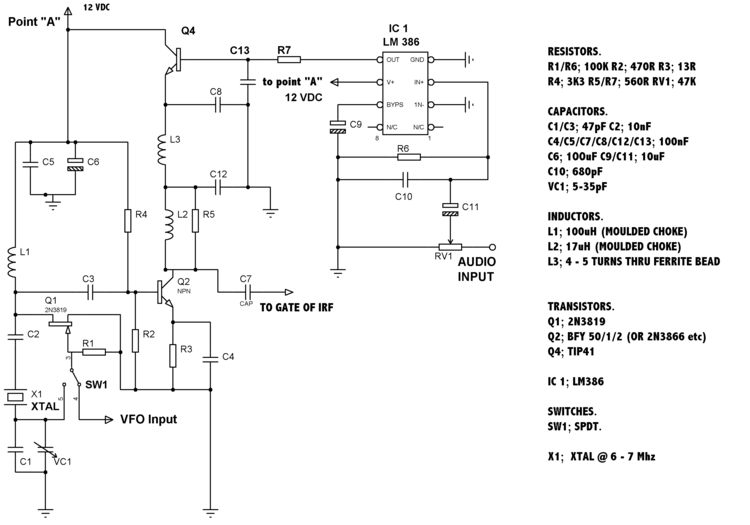
The first circuit is of the oscillator/ modulated driver stages. A LM386 audio IC is used to series modulate Q2. The LM386's output on pin 5, sits at half the supply voltage. But is swung plus and minus with the audio being fed to it's input.The addition of Q4 in the new circuit allows Q2 to draw more current without damaging the LM386.
The circuit without Q4 is normally ok for most cases though.
The second circuit is of the PA and filter sections. To set up you should, by adjusting RV2, set the DC voltage at TP1 to 2.5 VDC. Then by moving the turns on L6 further apart or closer together, get the RF power to read 10 Watts.
It must be noted that Q2,Q3 & Q4 must have heatsinks and that
Q3 & Q4 should be mounted using a TO220 insulation kit.
The third circuit shows the optional VFO. Values given will work over 6 to 8 MHz.
VFO Values for other bands are shown below.
|


