
Introduction
This article includes information on improving the sensitivity and total noise figure of VHF/UHF DX receiving systems. There are various ways of improving the quality of weak VHF and UHF RF signals. Emphasis is placed on reducing the internal noise floor and increasing the signal-to-noise ratio.
Tunable RF preamplifiers
Most tunable RF preamplifiers use 'set and forget' small input and output trimmer capacitors. For TV and FM DXers, this is inconvenient because unlike 50, 144, and 432 MHz hams, we are interested in peaking several different frequencies. Hence, varactor (varicap) tuning is very useful for rapid tuning.
Tunable RF preamplifiers are useful for reducing or eliminating cross-modulation and intermodulation distortion (IMD) problems. Also, by only amplifying a relatively small RF bandwidth, the strong signal handling and dynamic range performance is improved.
Why use a preamplifier?
DXers generally only need to use a RF preamplifier if their TV or scanner/tuner/receiver has relatively poor RF sensitivity. The second reason is because of long cable lengths which can result in heavy signal attenuation if a preamplifier is not used at the masthead.
If you live in a high noise area where the external man-made and atmospheric noise floor is greater than 4db at 50 MHz, preamplifiers will offer little or no improvement to weak signals. For example, man-made electrical interference from neighbours is often high enough to negate the benefits of any low-noise RF preamplifier. Also, on certain days, power line noise can be as high as S5. When external noise is this high, indoor or masthead preamplifiers can not improve weak signals. Apart from re-locating to a rural area, little can be done to combat this problem. Highly directional antenna systems, coupled with appropriate polarization, can often reduce man-made QRM. Receiver noise blankers and phase cancellation can also help, but these techniques are beyond the scope of this article.
At 45-220 MHz frequencies, external man-made noise will generally be no lower than around 2dB in city or suburban areas. Masthead TV preamplifiers with noise figures lower than 2dB are not really beneficial at VHF, because the antenna receives a constant background noise of 2dB or more. Only in quiet rural areas will background noise be below 2dB at VHF frequencies.
If narrow IF receiver bandwidths are used, for example 2.4 KHz SSB, the internal noise floor is lower; hence masthead preamplifiers with noise figures below 2dB are often beneficial at VHF. For example, 144 MHz weak signal hams often use a masthead preamp, which have a noise figure of typically 0.7dB.
At UHF frequencies, background noise is typically no greater than 2dB; hence masthead TV preamps with a 0.5dB noise figure can be beneficial.
RF Preamplifiers are not always needed
Just because a preamplifier can increase the S meter on your receiver, there is more involved. After installing a preamplifier, you may find spurious signals appear all over the dial! In this case the preamplifier overloads the RF and mixer stages. The probable cause(s) are excessive preamplifier RF gain, bandwidth, or inferior bipolar design, etc.
A poorly designed preamplifier can cause receiver problems, even though it might not degrade the basic performance of the receiver by causing overloading. The preamplifier could have high noise, and this could make weak signal reception worse than without the amplifier. Also, the preamplifier might be unstable (self-oscillating), which can cause all manner of unmodulated carriers to appear.
Will a preamplifier improve weak 88-108 MHz FM DX signals?
Receivers and tuners have a sensitivity threshold, which is the amount of RF input signal required to cause the receiver to produce something watchable or listenable. In 1948, the typical FM tuner had a sensitivity threshold of 30 microvolts. By 1952 it was down to 10 microvolts and improving each year. The sensitivity threshold is established by a number of factors of which the most important is the internal noise figure of the tuner. All 88-108 MHz FM tuners include an internal 88-108 MHz RF amplifier. The RF amplifier is the first active (electricity operated) "stage" in the tuner. It does two things: (1) It provides gain at the incoming frequency (88 - 108 MHz), and (2) it creates a threshold for the sensitivity of the receiver. The sensivity threshold is determined by many factors but the single most important is the "noise figure". Noise figure can be thought of as a wall - an electrical wall over which broadcast signals must climb before they can be heard. The lower the noise figure, the shorter the wall - i.e., a lower wall allows "shorter" (weaker) signals to exceed the height of the wall. When the broadcast signal is greater (higher than) the "noise figure wall" then you begin to have reception (something you can hear or see).
Modern FM tuners (post 1987) are capable of producing extremely weak reception you can just hear with signal inputs as low as 1/10th of a microvolt (0.1 uV). At 1 microvolt (1 uV), a quality tuner will produce enough FM quieting to enable almost noise-free reception. This high sensitivity performance is largely because the noise figure of tuners have reached a plateau. Assuming a superior ultra low noise tuner was used, external man-made and atmospheric noise is high enough that all you would hear with a lower noise figure (than we presently have available today) tuner is more noise - not more signal. External atmospheric and man-made noise is a wall as well - and when the tuner's internal noise figure wall is equal to or lower than the external noise wall, a preamplifier will not offer any improvement.
What happens when you place an preamplifier in front of an FM receiver or tuner? First, the noise figure of wideband preamplifiers is ALWAYS higher than the RF stage noise figure of low noise FM tuners. So by adding the preamplifier, you have just taken a backwards step to a higher/taller "noise wall" at your receiver which is not desirable. Next, the preamplifier has signal gain. Logic might tell you that if a signal is weak, "more gain" will give you better reception. Not true - the signal is weak because it is noise that is limiting the reception and now you place an even higher noise wall ahead of the FM receiver/tuner and - AND - you amplify the new higher noise wall as well as all of the FM band signals by 10-20-30 dB.
More signal is desirable if there is also less noise. More signal is good if in addition to there not being more noise there is also a capability in the FM receiver/tuner to handle more signal. Unfortunately, adding even 10 dB of additional gain into a properly designed FM band receiver/tuner system is a high guarantee the tuner will OVERLOAD. If you had FM cross-modulation and images (stations appearing at several dial spots) - BEFORE you added the external amplifier, your new wideband amplifier will create an even worse situation. The tunable BF981 preamplifier featured below will of course minimise this problem.
Now in the rare situation where you try an preamplifier and it actually improves FM reception, what is this telling you? (1) The FM receiver/tuner you are using is old, has a high noise figure, needs realignment, or should be trashed, or (2) you live in a quiet rural area with few local stations and have a receiver connected to a MosFET or GaAsFET preamplifier.
For DXers using modern (post 1987) MosFET RF front-end 88-108 MHz FM tuners with optimum alignment, RF preamplifiers will generally not improve weak FM signals. Although this statement may appear out of place in an article which includes BF981 construction preamplifiers, it is based on the author's own observations. More effort should be placed on using low loss coaxial cable and improved high gain directional antennas.
TV tuner sensitivity
Early TV sets, circa 1940, had very poor RF sensitivity. Bob Cooper recently commented that a receiver of that era required around 1,000 microvolts to produce a grainy image on the small screen, and RCA was recommending 5,000 microvolts. A modern TV set with 50 microvolts will produce a far better image than the 1936 version with 1,000 microvolts.
In the 1960s, TV tuner noise figures started to gradually improve, but were still inferior to some of today's sets. Typical TV tuner noise figures were around 10-13 dB. For this reason, low noise preamplifiers were more essential for 1950's and 60's TV sets.
The typical TV tuner noise figure for modern sets is 6-7 dB at 45-220 MHz VHF, and 10 dB at 470-860 MHz UHF.
For TV DX, the author uses a HS Publications D100 varicap 40-230 MHz TV tuner/RF converter. The D100 uses a Toshiba EG522F Mosfet varicap TV tuner. In most cases, I have found that a 2dB Mosfet tunable 45-70 MHz pre-amplifier offers little or no improvement on weak video signals. Why? Because at 45-70 MHz the RF noise figure of the EG522F TV tuner is low enough; hence external noise becomes the limiting factor. This can be proved by the simple test of plugging an outdoor aerial into the TV tuner's input, while watching a blank TV channel (noise on the screen). If noise on the TV screen shows an obvious increase, the tuner noise level is low enough, and hence a preamplifier will produce little or no improvement on weak signals. If however no increase in noise is observed, a preamplifier will be essential.
At frequencies above 88 MHz, external man-made and atmospheric noise is lower. For this reason, low noise pre-amplifiers are generally more beneficial for band 3 (170-230 MHz), and especially UHF TV.
During the early 1980's, the German company Telefunken introduced the ET021 Mosfet varicap TV tuner. The ET021 featured Mosfets in the RF and mixer stages of the VHF section, for use in areas subject to adjacent channel selectivity problems. Typical figures quoted for an interfering signal two channels away from the desired signal and to give a 1% cross-modulation on the desired signal are 100 mV as compared to a conventional varicap bipolar tuner with 25 mV (band 3 TV channels). The ET021 was a revolution in terms of strong signal handling and low noise RF performance.
The Toshiba EG522F varicap VHF/UHF TV tuner was introduced around 1987, and is also excellent in terms of strong-signal handling and low noise performance. Other Mosfet and GaAsfet TV tuners are currently available, for example, around 1989, Toshiba introduced a 3SK97 GaAs-MES-FET TV tuner.
88-108 MHz FM tuner sensitivity
The author's main FM DX tuner is the Onkyo T-9090 II. Since aligning all the RF and IF coils, the sensitivity is now optimum. Now that the tuner is at optimum sensitivity, a 2dB noise figure BF981 preamplifier will only offer a small improvement on weak signals. In contrast, if a tuner is relatively insensitive or needs aligning, a 2dB noise figure preamplifier can offer a significant improvement on weak signals.
During times of high external man-made or atmospheric noise, low noise preamplifiers will usually offer no improvement to weak 88-108 MHz FM signals. For this reason, a sensitive FM tuner, which has optimum alignment, usually will not need additional external RF pre-amplification.
The T-9090 II features a digital signal strength meter. By tuning to a blank channel, and connecting an external FM aerial, the signal strength meter indicates a higher dB reading. Under normal low noise conditions, the increase is approximately 2dB. If the meter increases by more than 3-4dB, external noise levels are high, hence a preamplifier will produce no improvement.
When using a preamp for 88-108 MHz FM DX, it is usually best to use the 'local' RF setting on a FM tuner. By using 'local', the tuner's RF sensitivity is slightly attenuated, typically by 10dB. This means that the total RF gain is reduced, hence dynamic range is improved.
By using the 'local' RF setting, the RF preamplifier will then provide the predominant noise contribution and signals will not be masked by mixer noise.
88-108 MHz FM scatter signals will average 1 to 5 microvolts typically at a distance of 250 miles, requiring a 0.5 microvolt sensitivity receiver and a 10-12 dBi gain antenna.
RDX Labs UA-700 wideband VHF pre-amplifier
In addition to the BF981 preamps, I also use a RDX Labs UA-700 (designed by Jim Dietrich, Kansas, USA) wide-band 40-230 MHz VHF GaAsfet pre-amplifier. Considering the RF input is untuned, the overload and image rejection specifications are very good. I use the UA-700 indoors, for permanent connection to my Icom R-8500 scanner. This effectively lowers the R-8500's RF front-end noise figure from (~ 6-8 dB) down to 2 dB.
The gain of the UA-700 preamp is 10dB at 45-108 MHz, and 15dB at 150-220 MHz. Low to medium RF gain is ideal for minimising preamp overload. This is partly why the UA-700 has unusually good overload immunity.
Cross-modulation and overload
Mosfet TV and FM tuners offer superior performance in terms of strong-signal handling and freedom from cross-modulation. Reference to the circuit diagram will reveal what types of transistors are used in the RF stage. For example, the ONKYO T-9090 II uses Toshiba 3SK114-Y dual-gate Mosfets (1.4 dB noise figure) for RF amplification. Another advantage of Mosfets is their superior low noise performance.
High quality scanners, for example, Icom R7000/7100/8500/9000 and AOR AR-5000 VHF/UHF scanning receivers all feature GaAs-MES-FETs in the RF front end, hence strong signal handling is good.
For most domestic DX receiving installations, the gain of any RF preamplifier should generally be no more than 20dB. Even with a masthead preamplifier, it is only required to overcome the feedline loss plus about 7dB extra gain. Between 10-15dB gain is usually the best compromise in terms of strong signal handling and dynamic range performance.
Another important key to minimizing overload is to only amplify a small bandwidth. My tunable BF981 88-108 MHz pre-amp, when peaked has a 2 MHz bandwidth. This means that only a small portion (2 MHz) is amplified of the total 88-108 MHz FM band. Overload problems are thus greatly reduced.
Total receive system noise figure
High gain antennas, low loss cable, and good receivers are the most important equipment for DX reception. RF pre-amplifiers are generally the least important consideration for serious 40-108 MHz DX work. However, because external noise levels are lower above 108 MHz, RF pre-amplifiers can offer considerable improvement to weak signals. For this reason, most 144 MHz and 432 MHz weak signal ham operators use low noise Mosfet or GaAsfet RF pre-amps. Generally speaking, mast mounted preamplifiers are recommended for DX work above 108 MHz.
Because the author uses relatively short runs of low loss Hills DSC2.1 75 ohm coax cable (2.3 dB loss @ 100 MHz per 100ft), all Mosfet pre-amps are used indoors near the receiver. Low loss coax cable is essential if the pre-amp is used indoors because every dB of coax cable feedline loss in front of the preamplifier will add that number of dB to the noise figure of the receive system. For example, if our antenna balun has 1dB loss, and the total length of coax cable has 3dB loss, we have 4dB signal loss (3+1=4). If our receiver has a noise figure of 7dB, we add 4dB, which gives us a total of 11dB. This figure (11dB) represents our total receiving system noise figure! In contrast, if we use a 2dB noise figure preamp at the antenna, which is preceded by a 1dB loss balun, our total system noise figure is only 3dB! Quite an improvement compared to 11dB!
Remember that a 6dB improvement is equivalent to making the original antenna system four times as large or going from one to four yagis!
At UHF, if a TV tuner has a noise figure of 10dB, the addition of a 0.5dB masthead preamplifier will improve the total receiving noise figure by approximately 9dB! This underscores why masthead mounting of UHF preamps is important.
By using a pre-amp indoors, only the noise figure of the receiver is improved. For example, a typical VHF receiver or scanner has a noise figure of approximately 6-8dB, depending on the RF front-end. By using a 2dB pre-amp, the effective noise figure of the receiver is lowered to approximately 2dB. With a mast-mounted pre-amp, the first active transistor in the pre-amplifier sets the system noise figure, after losses associated with the input balun.
The BF981 pre-amp can be used at the masthead. You will need to run a shielded wire containing the DC tuning voltage for the varicap diodes, up to the masthead. Make sure you have good RF de-coupling at the receiver end, to eliminate any RF on the DC line. The benefits of mounting the pre-amp at the masthead will be more noticeable above 108 MHz.
Bipolar transistor pre-amplifiers are usually unsuitable for serious DX reception, because of overload and cross-modulation problems. As a general rule, GaAsfet or Mosfet pre-amplifiers are the best option for weak signal reception. While GaAsfet pre-amplifiers feature very low noise figures, most TV and FM DXers will not really benefit. This is because the terrestrial noise floor is usually no lower than 2dB from 45-108 MHz. For this reason, Mosfet amps are more practical. Also, GaAsfet amps are very prone to static charges, which can destroy the device. Mosfets, on the other hand, feature protection diodes on the input, hence the device is fairly resistant to static charges.
I have built three BF981 pre-amps. One is for 45-70 MHz band 1 TV, 85-108 MHz band 2 FM, 170-230 MHz band 3 TV. The circuit is based around the Philips BF981 Mosfet transistor, which achieves a noise figure as low as 0.7dB at 200 MHz in an optimized circuit. My version features a more modest 1.5 dB noise figure, and a typical gain of 20dB.
The Philips data sheets give typical noise figures for the BF981 as 0.7 dB at 200 MHz and 0.6 dB at 600 MHz. Curves are provided for determining the source admittance necessary to obtain these optimum noise figures. This type of performance can only be obtained with a dedicated pre-amp tuned to a single frequency, for example, 144 MHz. Since minimum noise figure is dependant on a high L / low C ratio, any tunable pre-amp covering a 20 MHz bandwidth will likely have a 1.5 dB noise figure at best.
Circuit description of BF981 pre-amplifier
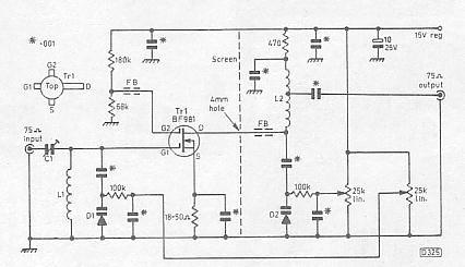
The 75 ohm RF input to gate 1 of Tr1, is tuned by L1 and D1. Tr1's drain is connected to a series tuned circuit consisting of L2 and D2. D1 and D2 are BB809 varicap diodes. For band 1 operation, L1 and L2 set the basic frequency, the bandwidth being adjustable from 2 MHz to over 6 MHz by means of the two 25K linear potentiometers, which adjust the bias applied to D1 and D2 (a bandwidth of less than 2 MHz might lead to instability). For band II and III operation, only use one 25K linear tuning potentiometer, since the lower Q (selectivity factor) enables a single 25K potentiometer for tuning D1 and D2. This is especially important on the 88-108 MHz FM version.
Coils L1 and L2 are wound close spaced (wire diameter) using 0.5-1mm (19-22swg) copper wire, eg, coaxial cable inner conductor. Inside diameter is 0.25 inch. L2 is tapped a third of the way down from the LT supply end to provide a reasonable 75 ohm match at the output.
Always try to maintain a high L/C ratio. For example, on the FM version, the maximum coverage should be 108 MHz MHz, with minimum capacitance applied from D1 and D2.
45-70 MHz: L1 (13 turns), L2 (12 turns).
The value of Tr1's source resistor should be adjusted to provide a current drain of about 10-12mA. The resistance may be anywhere between approximately 18-50 ohms. The D (drain) voltage should be approximately 10v, while the gate 2 voltage should be around 4v.
C1 is a 1-10pF trimmer: adjust for maximum output and minimum noise figure. I found the optimum setting was around 2pF (trimmer plates nearly unmeshed). It is very important that C1 is soldered directly on to the input connection pin. The lead length between C1 and G1 should be short as practicable.
L1 wire should be at least 0.5 mm diameter. I used 0.7 mm diameter coax cable inner conductor to reduce losses in the coil. Make sure L1 has a good connection to the copper board ground plane (earth).
Use 1/4 watt carbon resistors, and as in all VHF/UHF RF construction work, keep lead lengths to a practical minimum. The source resistor lead length should be as short as possible.
FB (ferrite bead) is simply slipped over the BF981 drain and G2 leads. This helps to suppress pre-amp oscillation. Ferrite beads can sometimes be salvaged from receiver IF transformers. Use a plastic alignment tool.
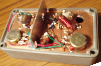
The pre-amps were built "dead-bug" style on a piece of unetched double-sided circuit board material. The copper foil acts as a ground plane, and all ground connections are made directly to it. See an example of typical low noise GaAsfet pre-amp construction.
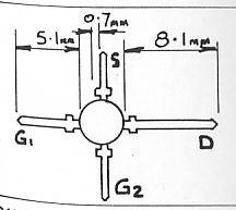
Anchor the double-sided copper board to the die-cast aluminum box via the coaxial socket nuts and bolts. Position the Mosfet on the input side of the screen, with only its drain lead going through to the output tuned circuit.
With minimum lead lengths, metal case (approximately 4.25 x 2.5 inches), and screening between the input and output circuits, there should be no instability or oscillation problems. Mount the components on a double-sided copper board bolted to the case. Die-cast boxes, even though more expensive, are recommended.
The metal shield (shown in dashed lines) helps prevent self-oscillation at or near the operating frequency. They isolate the input and output tuned circuits of each stage, thereby preventing unwanted stray coupling.
Those happier with traditional air-spaced variable capacitors, might like to try the Jackson C-82Y (3-20pF), deleting D1 and D2.
If the BB809 is not available, other varicap diodes can be substituted. However, they must be VHF/UHF types, with a relatively low minimum capacitance. 1pF to 30pF is the ultimate coverage. 5pF to ~ 30pF is more realistic. Make sure the minimum capacitance is no higher than approximately 6pF. The maximum capacitance should be no more than around 30dB.
88-108 MHz: L1 (6 turns), L2 (7 turns).
175-230 MHz: L1 (2 turns), L2 (2 turns).
Testing and setting up
FM version: Tune to the bottom of the FM band (88 MHz) and swing the tuning potentiometer. A noise peak should be seen, at the bottom of the tuning range. Next tune to the top of the band (108 MHz) and repeat the process. The noise peak should this time be near the top. If the low peak occurs near the middle of the control's range of travel, the coils have too much inductance and should be spread out a little more. Conversely if the high frequency peak is too near the bottom end of the range, the coils should be squeezed together to increase the inductance.
C1 can be adjusted for RF input bandwidth. For example, with C1 set to 1pF, the input bandwidth will be narrow (be careful of possible oscillation problems). If C1 is set to 5pF, the input bandwidth will be relatively wide.
Alignment for a given TV channel is simple. Tune the input coil L1 (adjust the spacing) to the video carrier frequency, and the output to coil L2 to the audio carrier frequency. Peak C1 for maximum output both before and after aligning L1 and L2. Higher gain with reduced bandwidth and thus better noise performance would be achieved by aligning both L1 and L2 to the video carrier frequency, though this would result in reduced picture definition and low TV audio output.
Power supply
The writer uses a conventional 18v DC plug pack. A separate box has been constructed, containing:
15v DC regulator (at least 17.2v DC is needed on the input of the regulator).
Various filter capacitors.
Four output DC sockets for feeding 15V filtered DC to all my pre-amps. For more information on power filtering, refer to the VHF section in the ARRL handbook.

Parts list for tunable BF981 pre-amp
Resistors (1/4 watt): 180K, 68K, 100K, 470ohm, 18-50ohm.
Capacitors: .001 (1,000pF) ceramic (9).
10uF electrolytic capacitor.
C1 1-5pF small trimmer (10pF max).
BB809 VHF variable capacitance diode (2). Similar specification varicap diodes can also be used. Any VHF varicap diode that covers ~1-20pf will be suitable.
25K linear potentiometer (2).
FB (ferrite bead) (2).
Philips BF981 Mosfet.
Wideband operation
If wide-band coverage is required, for example, 45-70 MHz, the varicap diodes and 100K resistors are left out. L1 is tuned to the lowest desired frequency, and L2 is tuned to the highest desired frequency. This means a 1-30pF trimmer is used for the input and output coils. Once aligned, the trimmers don't need to be re-adjusted.
Mosfets preamps designed for wide-band frequency coverage, typically have reduced gain compared to narrow-band versions.
Parts availability
BB809 varicap diodes and BF981 transistors are available from Maineline Electronics (UK).

BB809 varicap diode specifications
Vr (maximum) voltage 28 volts.
pF/V: 42pF/1.0v.
pf/V: 2.8pF/28v.
Q ratio: 8.0
Conclusion
For more details on Mosfet and GaAsfet pre-amplifier construction techniques, consult the ARRL handbook. The 1989 edition (chapter 31 VHF radio equipment, features several pre-amp designs). ARRL handbook editions produced before 1993 seem to have more relevant information.
Links
Using the BF981 low noise VHF pre-amp for 144 MHz by Gordon Mcdonald, VK2ZAB.
Determinants of receiver sensitivity - What are the keys to better weak signal receive performance by Doug McArthur, VK3UM.
Low noise ATV pre-amps by Clint Turner KA7OEI.
Typical low noise VHF pre-amp design by Dave Blaschke, W5UN.
Understanding pre-amps by Paul Shuch, N6TX.
Preamplifier design by SM5BSZ .
References
T.Emslie, Low noise VHF pre-amplifier, Television Magazine, September 1997, Page 829.