 |
|
 |
 |
| Welcome to the Work Bench. This is where the projects will be displayed. This will be a step by step process in which you are more than welcome to follow, or just watch from time to time. |
| The first project on the bench is something I have been needing for some time. A mobile amplifier that will give me a solid 500 watts pep from 15 - 80 meters. I could have gone out and purchased something to fulfill my needs, but I would rather learn from building one. Cost was another thing. Since I love what radio has to offer, I have accumulated alot of spare parts. It is from this resource that the project will pool from. This pooling will cut my costs conderably. You can click on any picture to see a larger view. Okay, on with the project. |
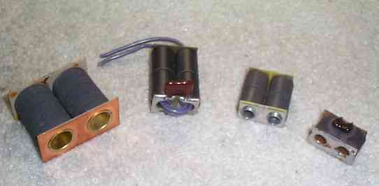
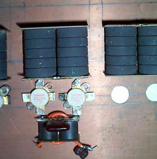
| The transistors to be employed in this project are the Toshiba 2SC2290 and the 2SC2879 (SI=N 45V 25A PEP=100W 28 MHz). |
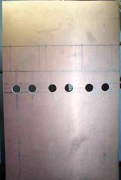
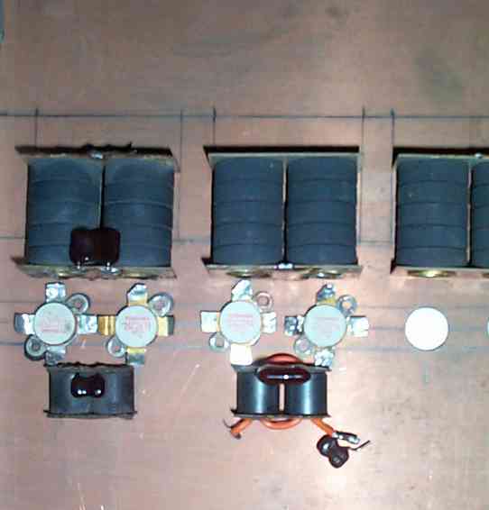
| The foundation of the project will be centered around a copper clad fiberglass board. The holes have already been drilled using a 1/2 drill bit. This one is cut to the measurements 7 1/2 inches wide by 11 3/8" inches long to accomodate the heat sink. The holes for the 2290's haven't been drilled yet. This project will use two 2290's to excite six 2879's. |
| I do have a desktop drill press. This helps me drill holes easily. However, if there isn't a drill press available, then be very careful drilling the holes freehand. Be patient when drilling and there shouldn't be any problems. Caution: Small drill bits break very easily. |
| This project is for educational purposes only. As per FCC rules no amplifier can be run in Class D Service. I assume no responsibility for any duplication of the above. If done so, it is done at your own risk. |
| Since this is not a precision job, there will be some variances in the exact position of the transistors on the board. I do not have a CNC or a machine shop here at the shack. The spacing of the transistor mounting holes will depend on the output tranformers you will use. The width will be a factor here as well as height. The heatsink to be used in this project was acquire from ebay. The cost was $26 not including shipping (availability will be dependent on what is being offered for auction). |
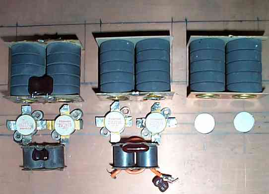
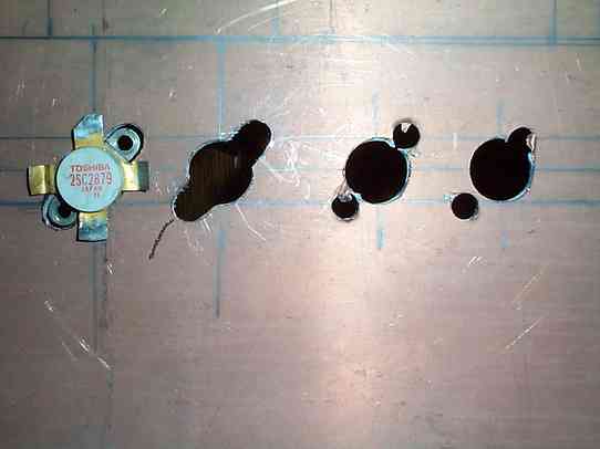
| Look at the above photo. Notice there are line drawings on the copper side of the board. These lines are the ploted positions for the output transformer (xfmr). This allowed me to space the transistor (xsistor) holes in proportion to the output xfmrs. This is not an exact science. But with some patience and lying the parts on the board I can position parts to make the appropiate adjustments. Carefully, look at pictures 3, 4, 5, and 6. |
| The heatsink has arrived. Now it is time to finish preparing the copper board to accomodate the heatsink. |
 |
 |
 |
 |
 |
 |
 |
 |
 |
 |
| 1 2 3 4 5 6 |
 |
 |
 |
| 7 8 10 11 12 13 |
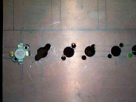
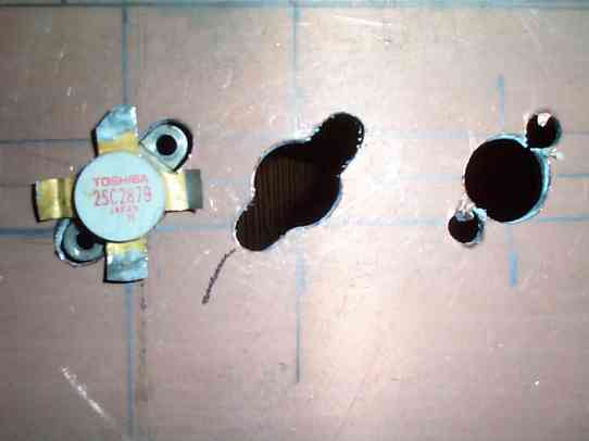
| In Pictures 7, 8, 10, the holes are in their beginning stages of being formed. In Pictures 11, 12, 13 the rough cuts and Dremel work has been finished. Filing the openings will be the finishing process for xsistor holes. |
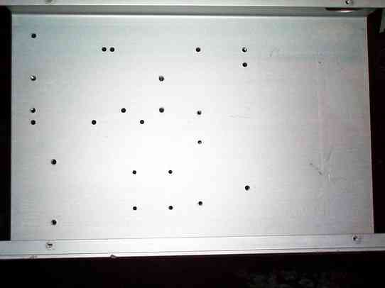
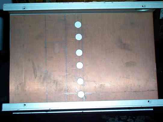
| Look at Picture 1. Notice that the heatsink is already drilled. Remember, this is a used heatsink and was applicable to another project. Picture 2 shows the xsistor holes on the copper board with no predrilled holes showing. The plotting of the board took this into consideration and the holes were drilled so that the xsistors would have a solid aluminum surface to be mounted to. This will assure good heat tranfer for the xsistors. The driver section will be mounted on the same board and plotting this section will come later. The next step is to complete the xsistor holes for the final amp section. The holes will be form fitted to the xsistors. The outside of the xsistor was traced with marker. This will provide a template when shaping the holes with a Dremel tool . The flange of the xsistor template will be drilled out first with a 7/32 drill bit. This predrilled hole saves time when it comes time to use the Dremel tool. I cannot stress the importance of taking your time. A mistake can mean the difference between a usable copper board and one that becomes a candidate for the scrap bin. |
 |
 |
 |
| When working with the template holes, it is easier to use the Dremel tool from the rear of the board. Doing so will avoid a miss like the one seen in Pictures 8, 10. The bit used for the finishing flanges can be found in any hardware store that carries Dremel tool accessories. If you have a steady hand you will be able to produce some excellent results. Although this is a homebrew project your workmanship will be displayed for those you chose to show it to. The better is looks, the better it looks on you. Well, on to the next page. It is time to move on to some more. The alignment of the driver section will be next. Once that is done, the finishing touches to the board will begin to take shape. This project is going to be done using a hybrid of Surface Mount Technology. No more cutting on the board will be necessary once the driver section is finished. You'll see. Okay, let's move on to the next page. |
| Board Prep |