Unified Semantic Model for Types, Attributes, Relationships and Behaviors
Author: Kenny Yu, PhD
Unified Semantic Model for Types, Attributes, Relationships and Behaviors
Modeling techniques lack relationship semantics.
Modeling deficiencies hamper software development
Semantics and management of relationships
Comparisons with other technologies at the database level
Comparison with object-oriented analysis and design
Applicability and Performance considerations
Detailed Example of implementation in a banking application
Book loan from a network of libraries
Data or knowledge management systems
Modeling methodology is established that provides infrastructural service for managing entities, their types, attributes, relationships and behaviors with expressive relationship semantics. The model dynamically evolves to reflect changes and growth of the physical and conceptual systems being modeled. The model drives the process and registers the results of software analysis, design and development.
Modeling techniques lack relationship semantics
The relational model describes relationships between two types with a foreign key constraint, which in many cases is inadequate. In a sample database that is supplied with MS Access, the relationships of [Customer – Order] and [Category – Product] are both modeled with one-to-many relationships. These two relationships, however, are different in that an order has definitive existential dependency on a customer while a category of a product may be arbitrary and re-assigned.
While UML expresses relationships as composition and aggregation, implementing them fully in a programming language is a non-trivial matter. The instantiation of the composite object should be dependent on the composing object, and the removal of the latter should clear the former. In Java, for example, to fully express a compositional relationship, such as the one between order and order item, one needs to hide the public constructor of item and ensure that only the order object can create the item. Removing the order should nullify the item. Such efforts can only be achieved through laborious coding due to lack of relationship management mechanism in the language.
Modeling deficiencies hamper software development
The existing technologies require full knowledge of the system to be modeled. The resultant models are static and inflexible. On a relational database, tables, columns and constraints need to be added or modified. At the application level, classes need to be modified and recompiled. The modeling methods are only applicable to well-defined systems and lack the ability to accommodate additional requirements after the design is finished. If a subject system is less than perfectly defined, the analysis and design is obsolete as soon as they are finished. The model is often incomplete because
- Some aspects of the system are unknown at the time of analysis
- The requirements for the design do not cover all the aspects in avoidance of complexity
- Some requirements are modified to reflect new knowledge on the system.
The forms of incompleteness and incorrectness may be:
- Not all types are modeled. For example, the model for customer only describes retail customer with no provision for wholesale customers.
- Some attributes are not modeled. For example, in the model, a customer may have a phone number and an address. Further analysis reveals that a customer may have a home address, a mailing address at work and a vacation home address. Beside the home phone number, a customer may prefer to be reached at a mobile phone or a pager number.
- Some relationships are not modeled. Further analysis requires the relationship of a customer with a competitor be included such that incentive for conversion can be offered.
- Some behaviors are missing in the original model. For example, a customer places an add-on order and requests bulk discount in which case the current order need be linked to a previous one to qualify for the discount.
- Parts of the model are no longer valid.
One has to assume, from the examples cited above, that the understanding of a system of reality is dynamic, fluid and evolving. It is not possible to describe such a system with static models. The methodology employed in software analysis and design, at object level with UML, Java, C++, XML and at persistence with relational database tables and database constraints, are inadequate.
Proposed Solution
Elements of the model
The typing of entities is an evolving process. An entity may be of 0, 1 or many types. It may also devolve to lose its types. New types can be created on demand at runtime. Existing types may evolve to assume additional features. The author terms these features amorphous typing. These features reflect the dynamic nature of any realistic system. For example, when a person is born, she acquires a name and an id, likely a social security number and assumes relationships with her parents. Over time, she establishes relationships with a pediatrician, teachers and friends, assumes types of student, customer, employee, manager and learns to walk, talk and work.
The elements of the model can be summarized as follows:
- Attributes exist independent of and cross types.
- Relationships are defined between two or more types.
- Behaviors are defined independently of and cross types.
- Types may form a hierarchical structure on which a type may be a subtype to another type. The subtype inherits the attributes, behaviors and relationships from the super type.
Subsystems
Therefore, the model has three subsystems:
- Definition subsystem, which covers the definition of types, attributes, behaviors and relationships. This subsystem is to be utilized by an analyst who is versed in software design methodology.
- Assignment subsystem, which links entities, attributes, behaviors and relationships to entity types. Entities, attributes and behaviors can be assigned to multiple types. One relationship links two or more types. This is to be managed and configured by a system administrator.
- Data subsystem, which stores the concrete entities and their attribute values, behavior records and relationship instances among individual entities. This is to be used by end users through graphical user interfaces.
The Definition subsystem
The contents of the definitions in the definition subsystem are described as follows:
- An entity type represents an identifier of the type. It may be linked to a parent type for the representation of the hierarchical structure. The structure [Person ---- Customer], [Person ---- Employee] and [Person ---- Contract Employee] represents four types on three levels of the hierarchy. A type at a lower level, a subtype inherits the attributes, relationships and behaviors from the type at the higher level, the supertype.
- An attribute is a holder of descriptive values. It has a name and a data type understood by the programming language in use. The data types are usually number (Age=18), date (hire_date = 1/1/91), binary (portrait photo or signature), text or from a value domain. An attribute may be multi-valued such that the values form a list. An attribute value is terminal in that it cannot have any associations with other entities and cannot have attributes to itself. The seemingly attribute (department = ‘HR’) should not be since a department likely has attributes like ‘location’ and has association with other types like ‘Project’. Categorical descriptions, such as country and state codes, should be modeled as types that form relationships with other types. A person’s address would be a type that has a relationship ‘State Code’ with ‘CA’ of type ‘State’. Anything that has attributes itself, such as a stock option account that has a vesting schedule and exercise prices, need be modeled as a type and related to other types in question.
- A behavior defines what changes an entity can cause in the system. For example, an employee’s “quit” behavior causes a ‘last_work_day’ to be set, payroll to issue a last check, his relationship with his department to be removed, etc. A behavior can also be used for validating entity creation.
- Relationship types. A relationship type describes the existential dependencies between types. The dependency between entities is examined at the time of their creation and removal.
Semantics and management of relationships
On the basis of dependency between two types (a primary and a secondary) of entities and the multiplicity on the primary end, most relationships fall in one of the six types:
- Composition, or mnemonically R1P for part-of, in which the creation of the secondary relies on the existence of the primary and removal of the primary necessitates the removal of the secondary. The independent existence of the secondary is meaningless, therefore, impossible. Examples are [budget and budget line item] and [book and chapter]. In a relational database management system, such relationship can be enforced with a foreign key and “on delete cascade” constraint.
- Derivation, or mnemonically R1D, in which the creation of the secondary relies on the existence of the primary and removal of the primary fails if the secondary exists. Existence of the primary is independent but that of the secondary is fully dependent. Examples are [committee and meeting] and [meeting and minutes]. In an RDBMS, such relationship can be enforced with a foreign key with no cascade constraint.
- Hybridization, or mnemonically RH, in which the creation of the secondary relies on the existence of the primary and removal of the primary fails if the secondary exists. Existence of the primary is independent but that of the secondary is fully dependent. Similar to R1D except that more than one primary may join to produce the secondary. In an RDBMS, such relationship can be enforced with a mapping table that has a foreign key with a cascade constraint on the side of the secondary entity.
- Coagulation, or mnemonically RC, in which the creation of both the primary and the secondary are independent. Removal of the primary or the secondary fails if the primary-secondary relationship exists. The primary and the secondary are symmetrical in the relationship. If more than two entities join this type of relationship, a union entity need be created such that all participants form the same relationships with it. Therefore, this can be used to express n-nary relationships. In an RDBMS, such relationship can be enforced with a mapping table that has two foreign keys referencing the primary and the secondary entities with no cascade constraint.
- Utilization, or mnemonically RU, in which the creation of both the primary and the secondary are independent. Removal of the primary terminates the relationship but removal of the secondary, which is “in use”, fails if the primary-secondary relationship exists. In a RDBMS, such relationship can be partially enforced with a nullable foreign key with “on delete set null” constraint if there is one-to-many relationship between the primary and the secondary types. To prevent the secondary from being removed a mapping table is required that has an “on delete cascade” foreign key to the primary and another foreign key with no cascade effect to the secondary. An example of such relationship is [class and instructor]. The instructor of a class need be replaced when the instructor quits.
- Association, or mnemonically RA, in which both the primary and the secondary entities can be created and removed independently. Removal on either end results in the termination of the relationship. In a RDBMS, such relationship is modeled with a mapping table with two foreign keys, referencing the primary and the secondary types with “on delete cascade” constraint. An example of such relationship is [class and student].
The terminology used here to describe the relationship may be inconsistent with usage in the literature and in the field of practice, which itself is often inconsistent. Confusions should be resolved with the definitions given above. The terms R1P, R1D, RH, RC, RU and RA may be preferred since confusions are caused mostly by the connotation of the English words.
In R1P and R1D relationships, the secondary entity can relate to only one primary. Multiple entities must be unified to yield the secondary. When two parents produce a child, there exists a complex relationship: [(Father, Mother) – RU —<> Marriage <>– R1D — Child]. RH, RC, RU and RA relationships allow the secondary to relate to multiple primaries. In RDBMS and UML terms, R1P and R1D represent one-to-many relationships. The others present many-to-many relationships.
The relationships and their possible implementation on RDBMS with the use of mapping tables are summarized in the following table. Columns 2 through 4 indicate the propagation on deletion. The header “Entity to primary” means on deletion of an entity propagate to the primary end of the relationship and so on.
|
Relation Type |
Entity to primary |
Entity to secondary |
Relation to entity |
Note |
|
R1P |
Cascade |
Cascade |
Cascade on secondary |
Deleting the primary entity propagates to the relationship and to the secondary. One primary for many secondary. |
|
R1D |
|
Cascade |
Cascade on secondary |
Deleting the secondary nullifies the relationship. One primary for many secondary. |
|
RH |
|
Cascade |
Cascade on secondary |
Deleting the secondary nullifies the relationship. Many primary for one secondary. |
|
RC |
|
|
|
Neither the primary nor the secondary can be deleted if a relationship exists. They must quit the relationship first. |
|
RU |
Cascade |
|
|
The primary can be deleted, nullifying the relationship. The secondary cannot. They must quit the relationship first. |
|
RA |
Cascade |
Cascade |
|
Both the primary and the secondary can be deleted, nullifying the relationship. |
The establishment of the six relationship types enables the architecture to provide their management as a system service to applications development and avoid elaborate and complex use of relational technologies such as multiple mapping tables and constraints, and therefore, numerous application-specific SQL statements for manipulating the data. Basic behaviors of entities are specified by the relationships they have with others. For example, different consequences ensue from a student dropping out of a class and an instructor quitting.
A relationship is defined between two types and therefore is binary and directed. A relationship may have a description and a label at each end for presentation. The data of a relationship may have a modifier, which is often an index value or coordinates. For example, while sugar has an [ingredient_of] relationship with a drink, the modifier may specify 250 grams/liter. The data type, or class, or the modifier is specified on the relationship. The instance of the class, which is represented in textual form, is recorded on the links, which are instances of the relationship linking the entities.
Not all of these relationships may exist in an application system. The designer may find that 2 to 3 relationships are present in a particular system and decide to disregard the others. All six relationship types identified and defined here for the sake of completeness.
The Assignment subsystem
The assignment subsystem establishes links among types, attributes, relationship types and behaviors. When an attribute is assigned to a type, it may assume a new name. The attribute amount may be referred to as balance on type Account, and netWorth on type Customer. A relationship is derived from a relationship type, has a name and may have labels on both ends, and may have a modifier class that defines a description on a relationship instance. Such description is needed, for example, in the relationship [document references book] to specify a page number of the book. A behavior, when assigned onto a type, may assume a new name for human comprehension.
Comparisons with other technologies at the database level
While the model of this work goes beyond a database model, comparisons with other database models serve to help understand its features.
At the database model level, the establishment and management of the relationships distinguish this architecture from existing models, as described in http://unixspace.com/context/databases.html. The hierarchical model only handles the R1P relationships. The relationship managed in the network model is the RU relationships defined here. The associative model handles RA relationships. The relational model, without the use of mapping tables, can handle R1P, R1D and partially RU. With the use of mapping tables, it can handle RA. However, the relational model requires a physical table for each class of entity, resulting in proliferation of entity tables and mapping tables that have to be managed by applications code. The defects of the method as described earlier in this work are obvious.
This model has the benefits the object-relational model offers because the attributes of a class can be of any data type. For example, the location of an object on a map can be modeled with an entity of GeoMap class and an RA relationship with the object.
The object-oriented database model has defects and limitations inherited from object-oriented analysis and design methodologies. OOA and OOD do not provide means for describing and managing the richness and complexities of relationships as we have discovered. More in-depth comparison with OOA/OOD is provided in a later section.
The semi-structured database model is the antithesis of this work in that it mixes the schema with the data. This work provides a high degree of separation between the definition of data and the data itself.
The context data model is a hybrid that can represent relational, hierarchical and network data structures. It does not separate the metadata and data content into three subsystems as this model does.
Comparison with object-oriented analysis and design
OOA/OOD has no mechanism for managing dynamic type creation and assignment; all type definitions must be coded and compiled. Its relationship management is inadequate and no service is available for controlling the creational and terminational dependencies. While UML can specify the cardinality of relationships, it only reflects the intention of the designer. Although it is possible to achieve dynamic attributes and behavior through design patterns, it is up to the developer to implement such patterns with no help at the programming language or platform level.
Implementation Examples
Implementation of the data model on a Relational Database
A relational database is not required for implementing this data model. This model, in fact, may not need a database server at all. The data model can be stored in flat files, XML files or serialized objects of the programming language used. However, using a relational database offers benefits: 1. Most readers are familiar with relational database notations, such as the entity relationship diagram, which help conveying the concepts; 2. The infrastructure of a relational database, including the unique constraint, referential integrity assurance mechanism and indexing schemes, facilitates the implementation; 3. There are established technologies, such as JDBC, for interfacing to the database from a programming language.
If implemented on a RDBMS, this architecture supersedes the relational model since it pre-creates all tables and constraints necessary for most applications. The developer simply identifies the types, attribute and relationships in the application to register them in the generalized model. He may choose to create additional specialized relational database objects such as tables and constraints in addition to what this architecture provides.
An implementation of this model is illustrated in Figure 1.
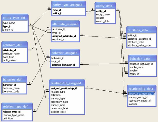
Figure 1 presents a simplified version of the implementation. Relations_type_def table has the six types identified in this work. Out of considerations such as performance and complexity, the tables attribute_data and relationship_data may be divided into more tables on the basis of types of the attributes and types of relationships. For example, the data for R1D and RH may be placed in one separate table since the relationships share the cascade constraint.
Implementation of the Application Programming Interface
While this generalized model can be used to complement, supplement, subsume or supercede object-oriented methodologies, including Unified Modeling Language and the programming languages with OOD features, such as Java, the notations and terms widely used in those technologies are helpful for conveying the concepts and structures of this model. Therefore, the data model is extended into the application programming layer and reified in the form of a set of Java API depicted in UML. The API outlines a language for describing and implementing the management of entities, types, relationships, attributes and behaviors.
The set of Java programming interface is illustrated in Figure2.

For an entity to assume a type, other entities, along with the type, are supplied to satisfy the requirements for R1P, R1D and RH relationships.
An application developer’s use of the API, in a simplified case, would involve:
- Retrieve EntityTypes from an EntityTypeManager
- Find entities by type from the EntityManager
- Create new entities from the EntityManager
- Have the new entities assume a type
- Set attribute values on the typed entities.
- Relate the new entities to others
Applicability and Performance considerations
For static, simple and isolated systems, which can be modeled with a few tables in a database, this modeling methodology does not offer significant benefits. This model solves the extensibility problems with large, complex and dynamic systems such as laboratory information management systems, chemical and bio-informatics, semantic networks, and drug interactions.
Since the model separates the meta-model, the model and the data, the performance is more easily managed. In cases where extremely large data sizes are involved, techniques for denormalization and materialized views are needed.
Detailed Example of implementation in a banking application
An example of implementation of this model is provided to illustrate the concepts and the techniques for analysis.
Example case
A bank has branch offices. Each branch has a manager and a number of cashiers. The manager is essential to the branch such that she can not be promoted out of it or quit without a replacement. Cashiers can come and go and can work for more than one branch. Customers open accounts at branches and conduct transactions at the home branch or other branches. Accounts may be jointly held. Some transactions are conducted through a cashier. The manager and the cashiers of a branch, as employees of the bank, receive employment benefits from the bank and only differ in the job roles at the branch.
Analysis of the data model elements
The following types can be identified, which are entered into the Entity_Type_def table as depicted in Figure 1.
|
Type |
Parent Type |
Note |
|
Bank |
|
The headquarter |
|
Branch |
|
Cannot exist without the bank |
|
Employee |
|
May relate to one or more branch |
|
Manager |
Employee |
Relates to one branch with RU, is an employee |
|
Cashier |
Employee |
Relates to one or more branches |
|
Customer |
|
Holds accounts and conducts transactions |
|
Transaction |
|
Relates to branches and cashiers |
The following relationships are identified, which are entered into the Relationship_assigned table as depicted in Figure 1.
|
Primary Type |
Secondary Type |
Relationship Type |
Primary Label |
Secondary Label |
|
Bank |
Branch |
R1P |
Branches |
Headquarter |
|
Branch |
Manager |
RU |
Manager |
Manager of |
|
Branch |
Cashier |
RA |
Cashiers |
Works at |
|
Employee |
Employee |
RU |
Subordinates |
Manager |
|
Account |
Employee |
RA |
Opened by |
Opened accounts |
|
Customer |
Account |
RH |
Accounts |
Owner |
|
Account |
Branch |
RA |
Opened at branch |
Opened accounts |
|
Account |
Transaction |
R1D |
Transactions |
Account |
|
Transaction |
Employee |
RA |
Performed by |
|
|
Transaction |
Branch |
RA |
Performed at |
|
The “Primary Label” is what appears on the graphical user interface on the view of the entity on the primary end. The display of a branch, for example, will show its manager next to the label “Manager”. The use of the labels on the user interface will be shown later in this section.
Attribute definitions are entered into the Attribute_Def table as depicted in Figure 1.
|
Attribute Name |
Data Type |
|
Address |
Text |
|
Amount |
USCurrency |
|
Employee No. |
Text |
The address attribute is assigned on Employee, Customer, Branch and Bank.
The amount attribute is assigned on Transaction and Account. On Transaction, a positive number indicates deposit and negative withdrawal. On account, it is the ending balance.
The Employee Number is assigned on Employee.
The above assignments are entered into the Attribute_assigned table as depicted in Figure 1.
Behavior definitions and assignments:
- Transact() to be assigned on Account
- CloseAccount() to be assigned on Account.
- Resign() to be assigned on Employee and Manager. Manager.resign() behavior triggers a replacement immediately.
Behavior definitions and assignments are entered into the Behavior_def and Behavior_assigned tables as depicted in Figure 1.
Implementation of the language elements
Since the model encapsulates most of the business logic, this layer performs calculations and links the user interface to the data model.
Implementation of the user interface
The user interface can reflect the dynamic and flexible nature of the data model. It allows the browsing of entities along the relationship links and presents all the relationships, types, attributes and behaviors.
An implementation of the user interface is presented in Figure 3.

Figure 3 User interfaces that draw data from the model
In Figure 3, the Branch view’s title, Overland Branch, is the branch’s name in the model. “Address” is an attribute; “Manager” is from the [Branch – Manager] relationship; “Cashier” is from the [Branch – Cashier] relationship. In the Account view, the title “Checking 3120017” is the account’s name. The field “Opened by is from the [Account – Employee] relationship; “Owner” from [Customer -- Account]; “Transactions” from [Account – Transaction]. The two buttons, “Transact” and “Close Account”, represent the two behaviors assigned on Account type. In the Employee view, to the right of the name “Michelle White” is the types the employee has assumed. “Address” and Employee No” are two attributes. “Manager” and “Works at” are from relationships. “Resign” is a behavior assign to Employee in the model.
All the text and list values as well as behavior definitions on the above three view are directly taken from the model without hard-coded values in the design of the user interface.
Applications
The cases listed below server to demonstrate procedures and techniques of applying the model to various systems. The applicability of the model is not limited to these cases
Kinship modeling
Kinship modeling tracks parent-child relationship across multiple generations. We identify the following entity types and attributes
Person, first name, last name, gender, birthday, birthplace
Coupling: Start Date, End Date, the name of a coupling is the concatenated forms of the name of the members.
The Coupling here is similar to marriage in that is produces children but different in that it is permanent as long as there is a child.
Relationships:
|
Primary Type |
Secondary Type |
Relationship Type |
Primary Label |
Secondary Label |
|
Coupling |
Person |
RU |
Family of |
Member of family |
|
Coupling |
Person |
R1D |
Parent of |
Child of |
While the [parent – coupling – child] relationships identified here seem looser than the alternative [parents – RH – child] relationship, it is actually more accurate because the parents to a child may be unknown. Given a person, the model can trace up on an RU relationship to find his parents and down on one or more R1D relationships to find his children.
Book loan from a network of libraries
A customer of a library can request inter-library loans from a library. A book has a home library that owns it. The librarian may assist the checkout. The following entity types are identified: Library, Book, Customer, Loan, and Librarian.
Relationships:
|
Primary Type |
Secondary Type |
Relationship Type |
Primary Label |
Secondary Label |
|
Book |
Loan |
RH |
On loan |
Books |
|
Library |
Loan |
RH |
Loans |
Checkout Library |
|
Customer |
Loan |
RH |
Has loan |
Borrower |
|
Library |
Book |
RA |
Owns |
Belongs to |
Data or knowledge management systems
Large sizes of data from heterogeneous sources need to be categorized as the first step of its management. Categorization facilitates navigation and searches. A typical example is content directories, such as Yahoo directory. The categories form intersecting hierarchical structures.
For example, there are three paths to the category [United State] from http://dir.yahoo.com/:
- Directory > Regional > U.S. States
- Directory > Regional > Countries > United States
- Directory > Regional > Regions > North America > Countries and Regions > United States
While each path is on a branch of hierarchical structure, the end nodes are identical. Therefore, for the purpose of content management like the one on Yahoo.com, we identify types
|
Type |
Note |
|
Directory |
The root of all categories |
|
Category |
Including unlimited levels of subdivision |
|
Web Site |
The site listings within a category |
|
|
|
Relationships
|
Primary Type |
Secondary Type |
Relationship Type |
Note |
|
Directory |
Category |
R1P |
Directory consists of categories |
|
Category |
Category |
R1P |
Category has subcategories |
|
Category |
Category |
RU |
Categories link to each other across hierarchies |
|
Category |
Web Site |
RA |
Web site listings place under category |
The RU relationship here describes the cross-linking of categories. Among the cross-linked ones, one is the primary, the deletion of which invalidates the link.
Simulation systems
The dimension of time can be easily added to the model to describe changes in all dimensions, including types, attributes and relationship over a time course. Each assignment and data can bear a time stamp. At the relational data model level, this is achieved by adding a datetime column to the xxx_assigned and xxx_data tables. The resultant model simulates the evolution of a complex system in detail.
Semantic networks
An implementation of semantic network is provided in Unified Medical Language System (UMLS) by National Library of Medicine (http://www.nlm.nih.gov/research/umls/META3.HTML#s30). The 2003AB release of the Semantic Network contains 135 semantic types and 54 relationships. One branch of the semantic types contains [Physical Object – Organism – Animal – Mammal – Human], for example. These semantic types are entity types in the context of this work. In the following table, the semantic relationships are categorized into relationship types define in this work. It is evident that the data or knowledge on the semantic network can be cast on to this model.
|
Semantic relationship |
Relationship type |
Note |
|
isa |
R1D |
|
|
associated_with |
RU |
Use the loosest for the high-level relationship. |
|
physically_related_to |
RU |
|
|
part_of |
R1P |
|
|
consists_of |
R1P |
|
|
contains |
R1P |
|
|
connected_to |
RU |
|
|
interconnects |
RC |
Can be RA if the connection is loose. |
|
branch_of |
R1P |
|
|
tributary_of |
R1P |
|
|
ingredient_of |
RU |
Ingredient may be shared. |
|
spatially_related_to |
RU |
|
|
location_of |
R1D |
|
|
adjacent_to |
RU |
|
|
surrounds |
RU |
|
|
traverses |
RU |
|
|
functionally_related_to |
RU |
|
|
affects |
RU |
|
|
manages |
RU |
|
|
treats |
RU |
|
|
disrupts |
RU |
|
|
complicates |
RU |
|
|
interacts_with |
RC |
|
|
prevents |
RU |
Need a type or attribute of Absence. |
|
brings_about |
R1D |
|
|
produces |
R1D |
|
|
causes |
R1D |
|
|
performs |
R1D |
|
|
occurs_in |
R1D |
|
|
uses |
RU |
|
|
manifestation_of |
RU |
|
|
indicates |
RU |
|
|
result_of |
R1D |
|
|
temporally_related_to |
RU |
|
|
co_occurs_with |
RC |
|
|
precedes |
RU |
|
|
conceptually_related_to |
RU |
|
|
evaluation_of |
RU |
|
|
degree_of |
RU |
|
|
analyzes |
RU |
|
|
measurement_of |
RU |
|
|
measures |
RU |
|
|
diagnoses |
RU |
|
|
property_of |
RU |
May be modeled as attribute. |
|
derivative_of |
R1D |
|
|
developmental_form_of |
R1D |
|
|
method_of |
R1D |
|
|
conceptual_part_of |
R1D |
|
|
issue_in |
R1D |
|
Secured Data Management
Since all entities can be placed in a flat structure, separate from the type information, it is convenient to attach a security code to each of them. The code determines a user’s access permission on the entities, such as the ability to modify the attributes, relationships, on the basis of the user’s role and group affiliations.
Conclusions
The methodology unifies modeling at the object and the persistence layers, provides semantics and management infrastructure for types, attributes, relationships, and behaviors. It is suitable for modeling and application development for large-scale, complex and under-defined systems. The benefits include adaptiveness, reduced requirement for coding and ease of maintenance.
Supplementary Documents
Managing Conditions and Effects of Interactions