
To wet the appetite, first a few pictures of the box:


And when you open the box, you will find a surprisingly low parts count.
In Elapor foam: two fuse halves (held together with an elastic band in the picture),
two wing halves, a horizontal stab and elevator, a vertical stab and rudder, and a canopy.

A little bag of goodies, containing control horns, ailerons pushrods, EZ connectors
(including an Allenwrench), Velcro, rudder hinge, canopy hold-down-clips, and a ballast ball.

A real neat set of rudder and elevator pushrods, each consisting of a pushrod with z-bend,
an inner sleeve, and outer sleeve. There’s not going to be any binding there!

And to top it off, a geared motor and folding prop.

Oh yes, and a large sheet of gorgeous decalls. Mind you, you can decorate your Easy Glider in many
different ways. Elapor foam can be painted with a variety of waterbased spray paints and
felt tipped permanent markers.
One minor dissapointment was that nowhere in the manual is mentioned what motor it is,
what the gear is, and the size of the propelor.
Looking at the motor closely, I’d say it is a 6 volts speed400.

After some correspondence with
Jurgen Heilig
(one of the better informed persons on RCGroups on the subject
of Multiplex models),
this was confirmed. He also wrote that the gear is 3:1 and the propelor is a Hitec 9.5x5 folder.
Now that I had a second look, the motor assembly looks remarkably like the Hitec Sky Scooter
I briefly had. Well, I am a strong believer in “if it works, don’t fix it”, and the guys
and gals at Multiplex probably thought the same (great minds think alike). If it’s good enough
for the Sky Scooter, I’m sure it will be fine for the Easy Glider.
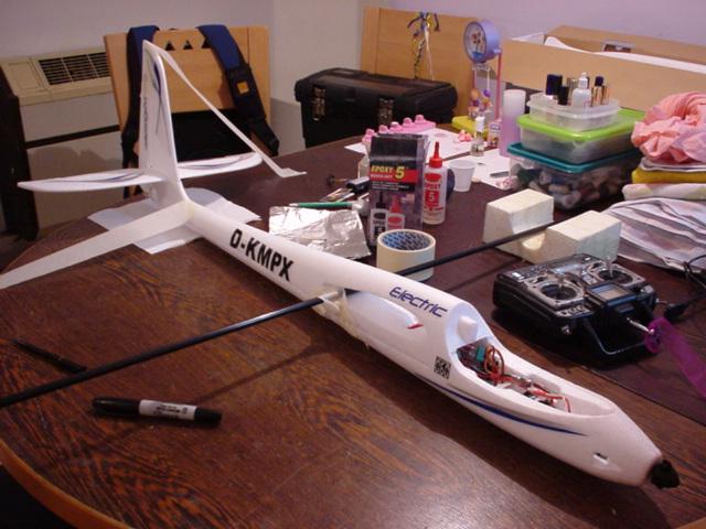
Since assembly starts with the fuse halves, I wanted to make sure that the motor worked properly.
So first I soldered a Castle Creations Pixie 20-P ESC to the motor. Since the motor is geared,
the wiring should be reversed. The ESC (+) wire should be attached to the (-) tab on the motor.
This is all explained in the manual. However, the manual does not show which tab is (+)
on the motor. Previous speed400 motors I’ve had, had a small red dot near the (+) tab, but
for the life of me, I couldn’t find any (+) indication.
Untill I took my glasses of, and had a close look at the tabs. There is a small grey
plastic sleeve where the tabs peep out of the can. One of these grey sleeves is slightly wider, and a tiny + appears on it.

The motor assembly fits perrrrfectly (duuuh). No need to glue the motor in place. This will also facilitate an easy motor change.

I then connected the ESC to a Rx and a battery to see if they all "spoke" with each other,
and if the motor turned the right direction (clockwise). They did. And get that surprised look of your face...

Before I continued, I just had to admire some of MPX’s molding ingenuity. The tail part of
the fuselage is divided in triangles. Weight saving, and strength inducing. Simple & smart.

A pushrod sleeve is glued down the center to pull the antenna through. An opening is molded in,
to lead the aileron servowiring to the Rx. The battery bay is molded in as well. The battery slides
in from the front, and sits right on top of the intended CG. Here you may want to trial fit your
chosen batterypack to see it fits, and to make any adjustments. The older wide packs from PolyQuest,
for instance, would not fit without some minor surgery.

Most Multiplex models I’ve seen are from molded Elapor foam. The molding process causes
the parts to come out of the mold with little raised “bubbles” in little circles at regular
intervals, as you can see here on the underside of the wing:

Also clearly visible is the under-chambered shape of the wing. This will facilitate in
nice slow flight, and improve the thermal-ability.
These bubbles will most likely NOT affect any flight behabiour, but being the stickler that I am,
I sanded them of. This realy is not a lot of work, but highly recommended. With a piece of
160-200 grit sandpaper, lightly make circular movements over the entire surface. Don’t
concentrate on the little bubbles only, or you will end up with “dents” in the surface.
Not only will your model look nicer, but any decall you want to stick on will stay on much
better and look nicer on a smooth base.

The pushrod sleeves for the rudder and elevator are glued in preformed “tunnels”
on the outside of each fuse half. Use thick CA and kicker here. The combination will help
a lot in stiffening the fuselage.

And when you glue in the pushrod sleeve on the inside, take care not to let any CA inside the
sleeves. Again, use thick CA here. I once tried to do something similar and used thin CA.
There are still little white bits of pushrod sleeve plastic stuck to the inside of the fuse of my Filip600…

It doesn’t say so in the manual, but I like to wrap my servos in masking tape before I glue them
into foam. It enables me to remove them relatively easily if/when I need to. The tape will
tear before the foam will break.
The rudder and elevator servos have a nice preformed little bay in each fuse half. I only needed
some very minor surgery to have them fit. There’s even a little space to lead the servowire up.
As suggested in the manual, I used a small blop of hot glue to keep them in place.


Once the fuse halves are glued together, the servos will sit nice and snug, engulfed in protective foam.

I was dreading the procedure of glueing the fuse halves together, but it turned out to be
a total non-event. First glue the “balance ball” in the correct fuse hole (thick CA and
kicker) near the rear end, and the motor retainer in the nose. These guys at Multiplex think
of everything. Unless you’re not going to use the standard motor setup, you’ll need a counterweight
in the tail to balance on the CG. If you are going to use any other motor setup, it would
be best to figure out the weight gain/loss vs the standard one, to see if you need any weight in the tail.
EDIT
Now, with 20/20 hindvision and about 100 flights behind me, there is NO NEED for the counter weight
ball if you are going to use Lipoly batteries (no matter what motor!!!).
Drizzle thick CA on ALL surface of the left fuse half, taking care not to get glue on
the motor/gear. Squirt kicker on the right fuse half. Wait a minute or so. Line up the “bumps”
and “holes” (remember Airfix™?), and press the two halves together. Work the fuse for a few
minutes as if you are making clay snakes. And you’re done.
Next glue in the canopy retainers in the rear of the cockpit.

And the rudder hinge at the tail end.


Next, the tail group. As with Airfix™ models, the parts fit together by lining up the bumps, and the holes…


Before glueing the horizontal and vertical stabs together, release the rudder and elevator,
and move them about for a while to loosen up the hinge.
The control horns and EZ-connectors where assembled, making sure the EZ-connectors
where on the correct side, and in the correct hole.

And CA’d into the pre-cut opening of the elevator.

Before glueing the rudder control horn in place, I cut the opening in the rudder for the hinge.

And then attached the control horn.

According to the manual, I now should glue the elevator and rudder together. Before doing that,
I decided to stick on some of the decalls, to see how well they stuck, and how they looked.
They looked pretty neat, so I left the decalls on, and glued the stabs together. Again, easy as pie.
Just some CA (without kicker this time, I wanted to be able to adjust the angle before the glue cures),
line up the holes and bumps, and stick together. Make sure you have 90* corners, or
you will be flying in circles!


I let this cure for half an hour or so. In the meantime, I couldn’t stop myself, and
choose some more decalls and attached them to the fuse. I think they look realy nice.
I also experimented a bit with a Magic Marker and decorated the canopy.

The manual tells me to attach the wingspar to the fuse with maskingtape, to properly line
up the tailgroup with the fuse.

After trial fitting the fuse/tailgroup a few times (getting the holes to line up, and the
rudder hinge to fit is slightly tricky), I taped the fuse to the diningroom table (with some
greaseproof paper under the tail), and mixed some 5 minute epoxy. I am sure that CA would be
fine here, but old habits die hard. I just prefered to use epoxy for this stage.
Epoxy duly mixed, I slathered a healthy amount on the tail, and then scraped about half
that amount of again, like you would do with wood filler. This way I would be sure that the
epoxy would penetrate the foam. I slid the tailgroup on to the fuse, and applied hand-pressure
for a minute or two. Then I taped the rudder stab to the table, and let it cure,
checking the angle several times.


The one thing I don’t have pictures of, is the ingenious Multiplex way of holding down
the canopy. You’ve seen the clips that I glued into the fuse, now all I had to do was to
glue two plastic sticks into two pre-cut openings in the canopy. Make sure you put them in
the right way! There’s a left one and a right one! Ask me how I know. I’ll give you a hint;
I don’t have pictures of this part of the assembly… On the bright side, I got to test first-hand
how to repair Elapor foam damage.
Done with the fuse. For the moment…
And now a few words about the wings.
The wings have a very distinctive shape. Since there are others who will be infinitely more
knowlegeable about the aerodynamic workings of the wing, I hesitate to go into too much detail.
Suffice it to say that the wings are THE most important part of an aeroplane.
The fuse can be a straight carbon fibre/wood/metal rod/stick/profile, round, square, or
any form; the wings are what make a plane fly.
As I mentioned before, the bottom of the wing has a distinct underchambered shape. This
will increase “lift” at low speed. However, turning at low speeds can be tricky. When
flying straight, the airspeed over both wings is equal. Now imagine your plane is flying a left
turn. The “outer” wing (right) is temporarily traveling faster through the air then the “inner”
wing (left). The airspeed on the outer wing is higher then on the inner wing. The closer to the
inner wing’s tip, the slower the airspeed. It can come to a point where the airspeed of the inner
wing is so low, that the wingshape can not produce enough lift anymore, and you will experience the
dreaded “tipstall”. The inner tip will fall out of the sky, dragging the plane with it. If you
have enough altitude that will be no problem. If you are just turning from crosswind into final
for landing, you are doomed (unless you are too high and plan on overshooting the runway,
or you fly a sturdy foamy).
Now look at the EasyGlider’s wingtips:


This particular shape helps the wingtip to “hold on” to the wind travelling over the surface,
thus preventing tipstall. Up to a certain point ofcourse. Slow down enough, and any wingshape
and/or form will stall!
The wingroots have a distinctive “jig-saw puzzle” shape. This will help keep things together
during those negative altitude passes, target practice, and other “sudden stop” manouevers.

Another nice feature of the wing is the servobay. Not only will your servo fit snugly, there
is a servoarm protector molded into the wing! And there is also a pre-cut servowire channel
to lead the wire to the fuse.

In this picture you can also clearly see the molding bubbles I so diligently sanded away after taking this picture…
As with the rudder and elevator servos, I wrapped the aileron servos in masking tape. The number
you see on the servo is the channel it will plug into in the Rx (obviously, on the plug-end of the
wire I stuck a label with the same number). Before commiting the servos to their respective
places, I verified their movement direction by plugging all servos into the Rx and setting up the
basics on my computer Tx. I don’t like surprises in the field…
I made my own servo extension wire, but you can just as easily buy two ready-made from your LHS.

It doesn’t say so in the instructions, but after hot glueing the servos in place, I put a small
strip of fibertape over the servo and the servo wires. Better safe then sorry.

Using some thin CA I glued the servo wiring in place.

And then closed the cover. Inside the –now covered- channel will later fit the wings’ 1 meter
long, carbon fiber, wing joiner.

Only now did I cut the ailerons free, and attached the control horns and EZ-connectors.
Although the Manual mentions aileron differential (more up then down movement) nothing is said
about affixing the aileron servo arm slightly forward. At first I set the servo arms straight(as per the manual),
but found it impossible to get to the recommended throws, even when using maximum ATV.
I took the servos out and moved the servo arms slightly forward, but the aileron pushrod
was too short to get even close to the 30 degree angle I wanted, so I had to make do with
an angle of about 15 degrees. More then enough to fly nicely, but not enough for aggressive flying.
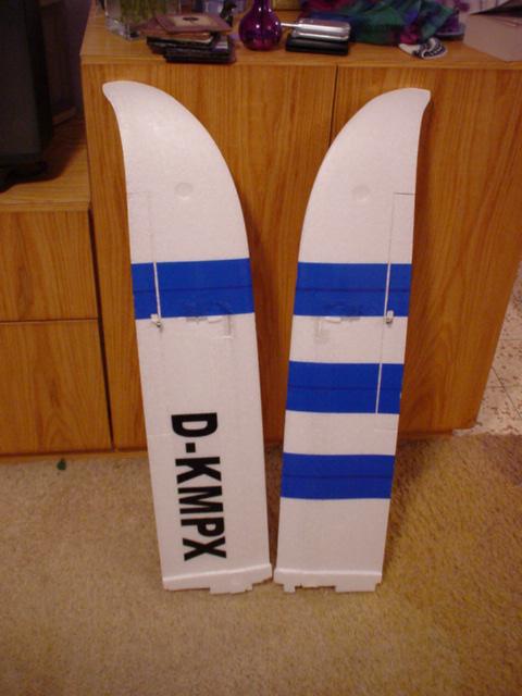
And now for a splash of color. A white wing’s underside does not induce visibility against
a light sky, so some dark blue striped were called for. I used normal packingtape that
I had left over from my Unicorn. And for some extra eye-candy, one of those decalls that came in the box.
Not to let the wings’ top surface feel left out, some more decalls here.

And the final product:
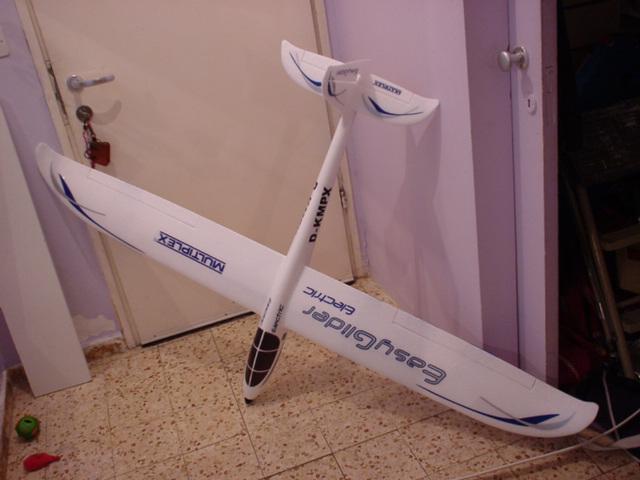

We have no nice soft grassy runways or landing areas here in Israel. The most I can hope for
is lots of loose sand with no stones in it. But more often than not it's a landing "on-the-rocks".
To protect the foam I taped 2" wide fibertape on the fuse's bottom (from the nose till the
aerial tube), and 1" wide fibertape on both wings' LE.
