Reflection of waves
Reflection of wave takes place when a wave strike an obstacle.
The wave will change its direction of propagation when it is reflected.
Characteristics of Reflection of waves:
- It obeys the Law of Reflection.
- The wavelength, λ of the reflected wave is the same as
that of the incident waves.
- The frequency, f of the reflected waves is the
same as that of the incident waves.
- Therefore
the speed, v of the reflected waves is the same as that of the incident
waves.
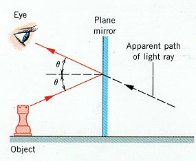
The phenomenon of reflection of waves obeys the Laws of
reflection:
-
the incident wave, the reflected wave and the Normal lie in
the same plane which is perpendicular to the reflecting surface at the point
of incident.
-
The angle of incident, i is equal to the angle of
reflection, r.
  |
 Angle of Reflection Angle of Reflection
= Angle of Incidence
Angles are measured with
respect to the normal line
(the perpendicular line).
|
Reflection of water waves
The phenomenon of reflection of water waves can be investigated using
a ripple
tank.  The water
waves are produced by a vibrating source on the water surface.
A horizontal bar will produced a plane wave.
 While a round source
will produce circular wave
Wavelength of a circular wave.

Study more about water wave here.
Video clips on ripple tank
Virtual lab on wave
Being a transverse wave, the crest of the water wave acts as a
convex lens that converge the light ray and produced a bright area on the white
paper. While the trough acts a concave lens that diverge light ray and produced
a dark area on the white paper. Hence a series of bright and dark regions are
produced on the white paper. A mechanical stroboscope is used to observed the
pattern of the reflected waves. The moving waves will appear to be stationary
when the frequency of the stroboscope is the same as the frequency of the water
waves. The frequency of the stroboscope = np, where n = the number of slits on
the stroboscope and p = the frequency of rotation of the
stroboscope (the number
of the stroboscope is turned in a second). View some
photographs taken by stroboscopic camera.
|
Characteristics of reflection of
wave: |
- angle of reflection = angle of incidence
- wavelength, frequency and speed of the wave do not change after
reflection.
- direction of propagation and velocity of wave changes.
|
Video clips on:
Reflection of light waves
Reflection of light on a Plain mirror
  |
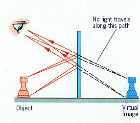
Light rays from an object
strike the surface of a plane mirror. The rays are reflected on the
mirror and appear to come from behind the mirror. The reflected rays are
drawn as if they are from the image. The image is virtual. Therefore the
rays behind the mirror do not exist. They are virtual rays and are
represented by dotted lines. The continuous lines from the mirror to the
eye indicates the reflected rays. The distance between the object and
the mirror is the same as the distance between the image and the mirror.
Characteristics of the image of a plane
mirror:
- Virtual
- Same size as the object
- laterally inverted
|
|
Application of reflection of light on plane mirror |
|
Defence & safety |
Telecommunication |
- A periscope is an optical instrument used to view
objects beyond obstacles. Light waves from an object which is incident
on a plane mirror in the periscope are reflected twice before entering
the eyes of the observer.
 
- The rear view mirror and side mirror in a car are used to view
cars behind and at the side while overtaking another car or making a
turn. The mirrors reflect light waves from the cars and objects into
the driver's eye.
- The lamp of a car emit light waves with minimum dispersion. The
light bulb is placed at the focal point of the parabolic reflector
of the car lamp so that the reflected light waves are parallel to
the principal axis of the reflector. Parallel light waves have a
further coverage (shines further).
|
- Optical fibres have many advantages compared to conventional
cables in the transmission of information. Optical fibres are light,
flexible, electrically non-conducting and can transmit much more
information.
- Infrared waves from a remote control of electrical equipment (TV
/ Radio) are reflected objects in the surroundings and received by
the TV or radio.
 |
Reflection of a curved mirror
|
If a concave mirror is thought of as being a slice of a sphere, then there
would be a line passing through the center of the sphere and attaching to
the mirror in the exact center of the mirror. This line is known as the
principal axis. The point in
the center of the sphere from which the mirror was sliced is known as the
center of curvature and is
denoted by the letter C in the
diagram below. The point on the mirror's surface where the principal axis
meets the mirror is known as the vertex
and is denoted by the letter A
in the diagram below. The vertex is the geometric center of the mirror.
Midway between the vertex and the center of curvature is a point known as
the focal point; the focal
point is denoted by the letter F
in the diagram below. The distance from the vertex to the center of
curvature is known as the radius of curvature
(represented by R).
The radius of curvature is the radius of the sphere from which the mirror
was cut. Finally, the distance from the mirror to the focal point is known
as the focal length
(represented by f). Since the
focal point is the midpoint of the line segment adjoining the vertex and the
center of curvature, the focal length would be one-half the radius of
curvature. |
Concave mirror |
Characteristics of image |
- Light rays from very far object are parallel. A real image is formed
at the Principle Focus.

|
- Real
- formed at Principle Focus
|
 |
- Object placed > 2f

|
|
|
|
- Object placed at 2f

|
- Real
- same size as the object
- Inverted
|
Rules of reflection of curved mirror
- Incident light rays that is parallel to the principle axis is reflected towards
the point Principle Focus, F.
- Any light ray that passes through the Principle Focus, F is reflected
parallel to the principle axis.
- Image is form at the point of intersection of 2 reflected rays.
Look at the animation below. |
- Object placed between f and 2f

|
- Real
- Diminished in size
- Inverted
|
 |
- Object placed at F

|
Image is formed at infinity |
| |
- Object is placed < f.

|
- Virtual
- Magnified
- Upright
At this position, concave mirror acts as a magnifying mirror.
|
 |
Convex mirror
 |
Image is always virtual, diminished, upright
irrespective of where the object is placed. |
Application of Reflection of a curved mirror
Application of the reflection of sound waves
-
Sonar (Sound Navigation and Ranging). Sonar is used to detect underwater objects (corals / fishes) or
to determine the depth of the water by means of an echo. Sonar
equipment emits a high frequency sound signal which is reflected by
the object in the water. The reflected sound wave is received by the
sonar receiver. The time taken for the echo to return is used to
determine the distance of the object below the water surface.


|
- The phenomenon of the reflection of sound wave is used to
determine the distance between 2 objects, eg. depth of a cave, well
or width
of a valley.

|


 Angle of Reflection
  The water
waves are produced by a vibrating source on the water surface.
 While a round source
will produce circular wave


 The
image of a convex mirror is always Virtual, Diminished, upright.
 The
image of a concave mirror depends on the object distance.
 A
convex mirror has a wider field of vision than a plane mirror. Therefore
it is used as a surveillance mirror and a blind corner mirror which is
placed at a sharp bend on a road.
 A
convex mirror is used as a side mirror of a car because it gives an
upright image and a wider field of vision than a plane mirror.
 Concave
mirror with long focal lengths can be used as makeup mirror, shaving
mirror or a dentist's mirror as they form magnified and upright image.
 A
dentist mirror
 The lamps of a car emit light waves with minimum dispersion. The
light bulb is placed at the focal point of the parabolic reflector
of the car lamp so that the reflected light waves are parallel to
the principal axis of the reflector. Parallel light waves shine far
and have a further coverage.


