How To Install A Remote Starter On A Generation 4 Camry
The following is a tutorial on how to install a remote starter and keyless entry system on a Generation 4 Toyota Camry. The installation I am explaining / depicting was done on my 1997 Toyota Camry with electric door locks from the factory, automatic transmission, no electric trunk release, and no existing security system. If you have manual door locks, a manual transmission, want a remote electric trunk release, or have an existing security system to bypass - then there will be extra things to do or install that will not be explained or depicted here - so please take that into consideration.
The system I installed was an Ultra Start (Model 125) that I got on eBay (December 2007). The ID of the seller I got it from was martinhod and I highly recommend him. He was helpful, shipped it to me fast, and sold me a great product at a very reasonable price. If you get this same exact system, then all of your wiring connections will be exactly the same colors as mine. If you don't, then the wires you are CONNECTING may be different colors than what I describe them as, but the wires you are connecting TO (depicted in pictures) will still be the same color as mine. Most systems call for you to access and make connections to the same basic wires, so this should work with just about any system. I only mention the exact system I used to explain the wires colors I will give (and because I have been very satisfied with it).
To install this system you will need a few basic tools. To test your wires and be certain you have the right ones, while not damaging anything in your cars electronics, you must have a digital multi-meter ($20 for a decent one at Wal-Mart). Anything else used to test your wiring (like a test light) can cause damage to your cars electronics. You also need a soldering iron (I used a $5 Wal-Mart one and it worked fine) with some solder (do not use the $1.50 Wal-Mart solder - I got some good solder from a NAPA store for like $6 and it worked fine). I had never soldered anything before, so do not be intimidated if you have not either. I would recommend you practice a few times (like I did) with some scrap pieces of wire in a well-lit and easily-accessible work space before attempting to solder your connections on your car while bent down in the floorboard. I include a few pictures of the proper soldering technique and it is not hard. During the course of installing this system I also needed:
- A good extension cord
- A worklight
- A piece of double-folded cardboard to ease my knees while knelt down on my concrete driveway
- Needle-nose pliers
- Wire-stripping / crimping pliers
- A utility knife (boxcutter)
- A Phillips head screwdriver
- A 10mm socket
- A 12mm socket
- Cable-ties (zip ties)
- 3M electrical tape
- Some wiring wrap (protective covering or split loom for wires)
- An extra 12 feet or so of 12 gauge automotive wire (for powering your module directly from the battery like I did if you so choose)
- A couple of electrical connection terminals:
- ONE 16-14g ring terminal that will fit on a 1/4" stud (your ground)
- TWO 12-10g ring terminals that will fit on a 3/8" stud (your power source if you power directly from your battery as I did)
- ONE 22-18g disconnect female (to slide onto the end of the hood switch).
To start off, you must remove some panels and covers to be able to access the wires you need to make connections to. Remember, it pays to label your bolts, screws, and clips OR lay them aside with the pieces they fastened (taping them together saves a lot of heartache).
Let's get down to business -

Remove this nut from the driver-side kick panel.

Pull the door trim out and away from the kick panel and remove the kick panel.

Remove this 10mm bolt that was under the door trim.

And this Phillips head screw from the other corner of this panel.

Then carefully pry off the upholstered panel you just removed the two screws from. Note the points where clips held the panel snapped into place (examples at red arrows) and make sure not to lose the metal clips. (The next few pictures show the procedure for removing / disconnecting the hood release from this panel). Once the upholstered panel has been removed, unclip the diagnostic connection (yellow arrow) and remove the four 10mm bolts (blue arrows) and remove this metal panel that is underneath the upholstered one.

Remove these two screws from underneath the hood release lever.

Then slide the lever assembly off and out.

Now slide the release cable anchor (red arrow) out of the slot it is in, bring the cable up out of the groove it is in, and slide the cable end out of the assembly sideways (blue arrow). The upholstered panel should now be completely free to move out of the way.

Turn the steering wheel hard to the left until you can see and remove the Phillips head screw on the left.

Do the same thing for the screw on the right. Also remove the third (and easily-seen) Phillips head screw that is on the underside of this steering column cover.

Remove the panel around the tilt mechanism by gently pushing it inward and out. Then thread the steering column cover over the tilt mechanism and remove it. You are now ready to find, test, and identify your wires.
FINDING THE CORRECT WIRES TO CONNECT TO
Even though I am going to show you exactly which wires to attach your system to (assuming you are doing this on an identical vehicle), you should still check these wires with a digital multi-meter to confirm that they are the right ones. Using the information I provide here you can also determine the right wires on other vehicles, provided that you check them with the digital multi-meter and look HERE for the wire colors/locations on your specific vehicle. To test each wire, you must configure your digital multi-meter to read DC current (instructions with the multi-meter should tell you how to do that), place the black (or whatever color yours may be) ground probe firmly on a ground (metal body of the car, wedged underneath the edge of an existing ground connection somewhere closeby), then use the other probe to pierce the insulation on the suspected wire - just stick it straight in but don't destroy the wire in the process - and get a reading on your multi-meter. I will tell you what each wire should read and under what conditions if it is the right one (like the starter wire should read ~12V but only in the start/crank position of the key, and read 0V in the ACC and ON positions of the key). By doing this correctly, you will ensure that your installation does not fail due to connecting to the wrong wire. You should route/cover/secure your wires in such a way so as to not interfere with any moving parts of your vehicle (like the steering column knuckle, pedals, etc), while protecting your wires from damage also. Remember that you must route your wires before soldering them together - once it is soldered on it is there. Also please remember that the wires must be connected where they go when you test them.

HORN - Look for this black connector underneath the steering wheel (where you removed the cover). The green / black stripe wire is the horn wire (better view in next pic). If this is the right wire it should read ~12V (approximately 12 volts) with the horn not being used and should drop to 0V when you hold down the horn. (On the Ultra Start 125 the wire I joined to this one was white / blue stripe on the 14 pin connector). After testing it, unplug it and pull it out where you can work on it. Always remember to press whatever little trigger there is on a connection like this so you can remove it without breaking it.

The horn wire.

PARKING LIGHTS - Look in the area that was covered by the kick panel and you will see this bundle of wires running along the floor from the direction of the rear of the car. This bundle will consist of several different-colored wires. The solid green wire is the parking lights wire. If this is the right wire it should read ~12V with the parking lights turned on, then 0V when they are turned off, then when turned back on the ~12V should not change more than 1V while turning the interior lights dimmer up and down. (On the Ultra Start 125 the wire I joined to this one was white on the 14 pin connector).
BRAKE SWITCH - The green / white stripe wire from this same bundle is your brake switch wire. If this is the right wire it should read ~12V with the brake pedal depressed and 0V with the brake pedal at rest. (On the Ultra Start 125 the wire I joined to this one was pink on the 14 pin connector).

Before you attach your wires for the tach signal, hood switch, and 12V current (if you run them directly to the battery like I did), you must run them through the firewall. I found this area to the side of the brake pedal area where the insulation was already precut for removal. There was nothing I would damage on the other side of this area when I gently hammer-tapped an old screwdriver against it to dent it and check, so I then knocked out a hole big enough to accommodate the wires you see running through the firewall. The two red ones are my 12V supply for power to the unit (I only hooked them to the battery after getting through with everything else though), the blue / white stripe one is my tach signal, and the green / white stripe one is my hood switch. This is what that area looks like from the engine well side.

HOOD SWITCH - This is the underside of the hood switch. I crimped and soldered a 22-18g disconnect female onto the end of my hood switch wire and then secured it to the male end of the hood switch (it was provided with my system). It is located in front of the driver (see next pic).


TACH SIGNAL - The system has to have a tach signal for it to know when your vehicle is cranked and running. I tried the wire color/location that was given in my manual and could not get a tach signal from it. I then went to the troubleshooting guide and it said that you can use a fuel injector wire to get a tach signal if the suggested wires do not work. The fuel injector wire did work for me, and is what I would recommend to save yourself some heartache (it is supposed to be one of the most reliable places to get a tach signal). The fuel injector wire you want to use (there are two to each injector) is the one that is not the common color. For instance, my car has four cylinders (and thus four fuel injectors). I peeled back some insulation to see what the wire colors were to all four and found them to be:
(white) AND (black / red stripe)
(yellow) AND (black / red stripe)
(green) AND (black / red stripe)
(blue) AND (black / red stripe)
So the color wire I would want to use would be the one that was NOT (black / red stripe) no matter which fuel injector I chose to use. I picked the injector all the way to the passenger's side just because it was easier to get my hand on to unclip and remove (remember about not damaging the clips that hold connectors on). Once you get your fuel injector unclipped and out to where you can reach it a little better, solder your tach signal wire onto it. (On the Ultra Start 125 the wire I joined to this one was blue / white stripe on the 14 pin connector). I did not check a reading on my meter from this wire but if you use a fuel injector wire you can't go wrong. Then tape this up and cover with protective wrap to protect the wires/connection from the high heat of the valve covers these are close to.

GROUND - This is the ground connection. This is right at the edge of the driver-side doorway about floor level. I crimped and soldered a 16-14g ring terminal onto the end of the ground wire. (On the Ultra Start 125 the wire I joined to this was black on the 14 pin connector).. I then removed the 10mm bolt and put the ground for my system (yellow arrow) on the bolt with the existing ground (red arrow) and fastened it back.

LOCK & UNLOCK - These are the door lock and unlock wires (next picture is a closeup of them). Disconnect the connection indicated and then they are more easy to get to and work with.
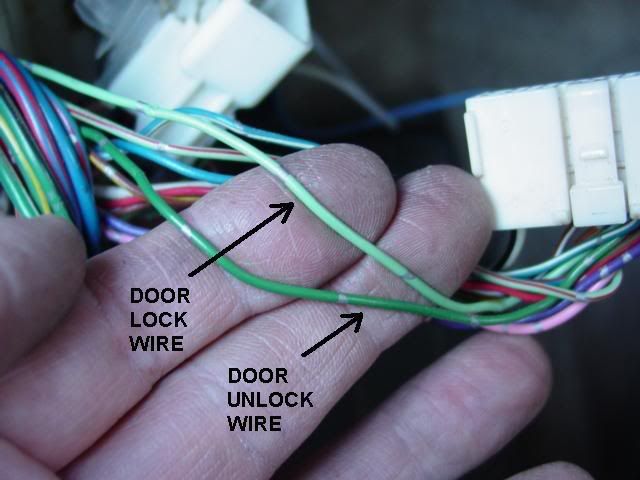
The door lock wire is light green. The door lock wire should read ~12V at rest and 0V while you hold the lock switch down continuously. (On the Ultra Start 125 the wire I joined to this one was green on the 2 wire white connector).
The door unlock wire is dark green. The door unlock wire should read ~12V at rest and 0V while you hold the unlock switch down continuously (On the Ultra Start 125 the wire I joined to this one was blue on the 2 wire white connector).

This is the ignition switch harness. It is located straight underneath where you put the key into the ignition. After you test all of the wires you need from this, disconnect it and pull it out toward you for easier access (I unwound some electrical tape from it to make this easier). On some of these wires you are going to be testing for voltage readings while starting (needing to hold the starter for more than just 1-2 seconds), so it helps to remove the EFI fuse that is located in the fuse panel under the hood right behind the battery. This keeps the car from actually starting while you hold the starter going for 4 or 5 seconds to get readings for different wires.
STARTER - The red wire is the starter wire. This wire should read 0V with the key in the "ON" and "ACC" positions and ~12V with the key in the "START" position. (On the Ultra Start 125 the wire I joined to this one was yellow on the 6 pin connector).
ACCESSORY - The blue / red stripe wire is the accessory wire. This wire should read ~12V with the key in the "ON" and "ACC" positions and 0V with the key in the "START" position. (On the Ultra Start 125 the wire I joined to this one was green on the 6 pin connector).
IGNITION - The black / red stripe wire is the ignition wire. There are two of these and it will work with either of them (I tried). This wire should read ~12V with the key in the "ON" and "START" positions. (On the Ultra Start 125 the wire I joined to this one was blue on the 6 pin connector). There is a secondary ignition wire that you must connect too (next step).
SECONDARY IGNITION - The black / yellow stripe wire is the secondary ignition. This wire should read the same as the first ignition wire. (On the Ultra Start 125 the wire I joined to this one was white on the 6 pin connector).
12V CONSTANT POWER - On the ignition switch harness, the other two unused wires (white and white / red stripe) are the 12V constant power source and you can tie onto these if you so choose. I chose to run some 12g copper wire through the firewall (the red wires in the firewall pics) to supply this directly from the battery. I crimped and soldered a 12-10g ring terminal onto the end of each of these red wires (extensions). I then soldered the extension wires onto the red wires from the 6 pin connector (12V supply wires for the control module), and made this connection at the battery last of all. (That way I could leave everything else hooked up to the control module while I was installing it).
SOLDERING YOUR WIRE CONNECTIONS THE RIGHT WAY
I had never soldered anything before, so I researched it and asked a couple of other guys I know who have experience with soldering. The following is a simplified version of what I gathered (and what worked well for me). You must have a soldering iron ($5 one from Wal-Mart is what I used) and some good quality resin core solder (I got some $6 solder from NAPA and it worked MUCH better than the cheap $1.50 Wal-Mart stuff I initially tried). The iron gets hot enough to burn you in less time than it takes to pull your hand away, and the solder material dripping off (if you put too much) is very hot also, so exercise caution with your hands/body and cover your carpet when you start to solder the connections in your vehicle. If you are like I was and are new to soldering, I do recommend that you get some scrap pieces of wire (stranded wire like you are going to be working on in your vehicle), get in a well-lit and comfortable area, and practice until you feel confident. That way you will not have a learning curve thrown at you while you are working with your wires on your vehicle while crouched in your floorboard with less than perfect lighting. Let's get ready to solder!

First you determine which wire you are going to be soldering another one onto. Once you have found the correct wire, determine where on that wire it would be easiest to get to as far as being able to comfortably do a good job of it while not burning yourself (or your car's interior). I found some wires in hard to reach areas and then traced them back to an easier to reach area to join them. You then need to strip off an area of insulation about 3/4" long. To do this without cutting and damaging the existing wire, you need to take your wire stripping pliers, determine the right gauge of the wire (guess too big before you guess too small so you don't cut the underlying wire), and cut through just the insulation in two places about 3/4" apart. Then, and very carefully so as not to hurt you or the wire underneath, take your boxcutter knife and score the piece of wiring insulation between the two places you cut through it. Do this until you can peel that piece of insulation off (needle-nose pliers come in handy here too). You now have a bare portion of wire where you can connect your wire from the system you are installing. You also must strip off insulation from the end of the wire you are going to attach. I stripped off more from this wire than from the first wire simply because you are going to have to have enough length to wrap around the first one at least 2 or 3 times.

Now tightly wrap the second wire around the first, making sure you wrap around it at least 2-3 times and that it is wrapped as tightly onto it as possible (for a good connection and heat transfer while soldering). You then want to hold the tip of your (preheated) soldering iron to the underside of the connection. The firmer you press against the connection the better it will heat it up to accept solder, so I ended up using my other hand most of the time to press the wires onto the soldering iron firmly (from an insulated area of course). You will continue to heat this connection and occasionally press a stick of your solder material onto the top of the connection. You do not want to touch the soldering material directly onto the soldering iron, but you want the iron to heat the connection to the point that it will melt solder. This is why you touch the solder material to the top of the connection. If it is not hot enough to melt the soldering material yet, remove the soldering material and continue heating the connection. Once the connection is hot enough to melt solder, you will notice the soldering material immediately melt when touched to the connection. It will melt and actually absorb downward into the connection (like in this picture), going in between the strands and disappearing. It will also wick outward from where it is in contact with the wires and spread throughout the naked wires. This makes a good solder that will be an excellent mechanical and conductive connection.
You should apply enough solder to fill in the gaps of the wires you are connecting and leave a nice shiny connection. The key is not having solder just on the outside of the connection (cold solder - if you melted the solder right off the iron and dripped it onto the connection), but having the solder "bond" the whole connection internally - inside the connection through and through. Once this connection is cool, you need to insulate it with a good coat of a quality electrical tape (like 3M / Scotch), covering beyond the edges of the wiring insulation so that the whole connection is covered, and pressed tightly around it as you encircle it.

Lastly, I routed my antenna wire from the control module and along the route I will depict in these next pictures, tucking everything behind the panels or headliner. I find an old credit card comes in very handy when pushing wires back behind panels or under the edge of the headliner, but sometimes you have to unsnap a panel to get something underneath it. The red dots in the following pictures will indicate where I ran the antenna wire.


Make your final connections now (either hooking the connectors up to the control module or hooking the 12V supply wires to the battery terminal). You are now ready to start it up! Follow the instructions for your system to set everything up. On this particular system, the first thing you do is acquire a tach signal, then program your remotes, set up preferences, etc. ENJOY! You may contact me at ycartf@yahoo.com if you have any questions about this.


