Galaxy Class Starship
U.S.S ENTERPRISE NCC-1701-D
Warp Propulsion Systems

Previous | Deck 36 | Next

Matter/Antimatter Reaction Assembly

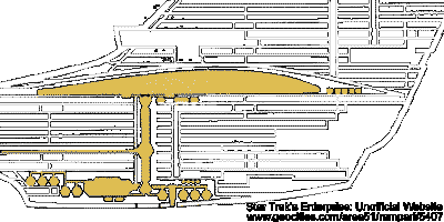
As the warp propulsion system is the heart of the USS Enterprise, the matter/antimatter reaction assembly (M/ARA) is the heart of the warp propulsion system. The M/ARA is variously called the warp reactor, warp engine core, or main engine core. Energy produced within the core is shared between its primary application, the propulsion of the starship, and the raw power requirements of other major ship systems. The M/ARA is the principal power-generating system because of the 10E6 times greater energy output of the matter/antimatter reaction over that of standard fusion, as found in the impulse propulsion system.

Matter/Antimatter Reaction System
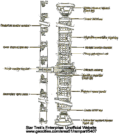

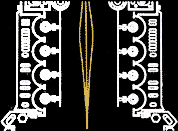
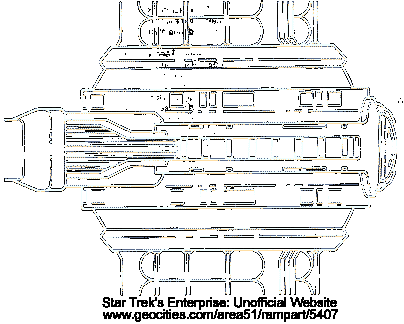
The M/ARA consists of four subsystems: reactant injectors, magnetic constriction segments, matter/antimatter reaction chamber, and power transfer conduits.

Matter/Antimatter Reaction Assembly
REACTANT INJECTORS
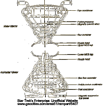
The reactant injectors prepare and feed precisely controlled streams of matter and antimatter into the core. The matter reactant injector (MRI) accepts supercold deuterium from the primary deuterium tankage (PDT) in the upper bulge of the Engineering Hull and partially preburns it in a continuous gas-fusion process. It then drives the resulting gases through a series of throttleable nozzles into the upper magnetic constriction segment. The MRI consists of a conical structural vessel 5.2 x 6.3 meters, constructed of disper strengthened woznium carbmolybdenide. Twenty-five attenuation cylinders connect it to the PDT and the major spacecraft framing members on Deck 30, maintaining 98% thermal isolation from the remainder of the Battle Section. In effect, the entire WPS "floats" within the hull in order to withstand 3x theoretical operational stresses.

Reactant Injectors
Reactant Injectors

Within the MRI are six redundant cross-fed sets of injectors, each injector consisting of twin deuterium inlet manifolds, fuel conditioners, fusion preburner, magnetic quench block, transfer duct/gas combiner, nozzle head, and related control hardware. Slush deuterium enters the inlet manifolds at controlled flow rates and passes to the conditioners, where heat is removed to bring the slush to just above the solid transition point. Micropellets are formed, preburned by magnetic pinch fusion, and sent down into the gas combiner, where the ionized gas products are now at 106K. The nozzle heads then focus, align, and propel the gas streams into the constriction segments. Should any of the nozzles fail, the combiner would continue to supply the remaining nozzles, which would dilate to accommodate the increased supply. Each nozzle measures 102 x 175 cm and is constructed of frumium-copper-yttrium 2343.

At the opposite end of the M/ARA lies the antimatter reactant injector (ARI). The internal design and operation of the ARI is distinctly different from that of the MRI, owing to the hazardous nature of the antimatter fuel. Every step in manipulating and injecting antihydrogen must be untaken with magnetic fields to isolate the fuel from the spacecraft structure (See: Antimatter Storage and Transfer). In some respects the ARI is a simpler device, requiring fewer moving components. However, the dangers inherent in handling antimatter necessitate uncompromising reliability in the mechanism. The ARI employs the same basic structural housing and shock attenuation struts as the MRI, with adaptations for magnetic suspension fuel tunnels. The housing contains three pulsed antimatter gas flow separators, which break up the incoming antihydrogen into small manageable packets to boost up into the lower constriction segments. Each flow separator leads into an injector nozzle, and each nozzle cycles open in response to computer control signals. Nozzle firing can follow complex sequences, resulting from equally compex equations governing reaction pressures, temperatures, and desired power output.
MAGNETIC CONSTRICTION SEGMENTS
The upper and lower magnetic constriction segments (MCS) constitute the central mass of the core. These components work to structurally support the matter/antimatter reaction chamber, provide a pressure vessel to maintain the proper core operating environment, and align the incoming matter and antimatter streams for combining within the matter/antimatter reaction chamber(M/ARC). The upper MCS measures 18 meters in length, the lower unit 12 meters. Both are 2.5 meters in diameter. A typical segment comprises eight sets of tension frame members, a toroidal pressure vessel wall, twelve sets of magnetic constrictor coils, and related power feed and control hardware. The constrictor coils are high-density, forced-matrix cobalt-lanthanide-boronite, with thirty-six active elements configured to provide maximum field strength only within the pressure vessel and permitting little or no field spillage into Engineering. The pressure vessel toroids are alternating layers of vapor-deposited carbonitic ferracite and transparent aluminum borosilicate. The vertical tension members are machined tritanium and cortenite reinforcing whiskers, and are phase transition-bonded in place as the vehicle frame is being assembled to produce a single unified structure. All engine frame members possess integral conduits for structural integrity field energy reinforcing under normal operation. The outermost transparent layer serves as one observable gauge ot engine pertormance, as harmless secondary photons are emitted from the inner layers, providing a visible blue glow. The peristaltic action and energy level of the constrictor coils can be readily seen by the Chief Engineer and/or deputy personnel.

Matter/Antimatter Reaction System
Magnetic Constriction Segments

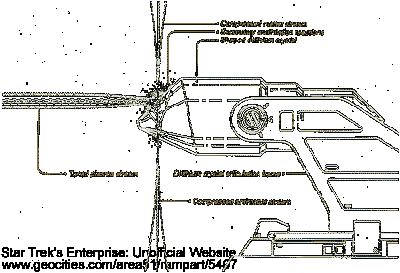
As the streams of matter and antimatter are released from their respective nozzles, the constrictor coils compress each stream in the Y axis and add between 200 and 300 m/sec velocity. This insures proper alignment and collision energy for them each to land on target within the M/ARC at their exact center of the chamber. It is at this spot that the M/A reaction is mediated by the dilithium crystal articulation frame.
MATTER/ANTIMATTER REACTION CHAMBER
The matter/antimatter reaction chamber (M/ARC) consists of two matched bell-shaped cavities which contain and redirect the primary reaction. The chamber measures 2.3 meters in height and 2.5 meters in diameter. It is constructed from twelve layers of hafnium 6 excelion-infused carbonitrium, phase-transition welded under a pressure of 31,000 kilopascals. The three outer layers are armored with acressenite arkenide for 10x overpressure protection, as are all interface joints to other pressu rebearing and energy-carrying parts of the system.

Matter/Antimatter Chamber

The equatorial band of the chamber contains the housing for the dilithium crystal articulation frame (DCAF). An armored hatch allows access to the DCAF for crystal replacement and adjustment. The DCAF consists of an EM-isolated cradle to hold approximately 1200 cm3 of dilithium crystal, plus two redundant sets of three-axis crystal orientation linkages. The crystal must be manipulated with six degrees of freedom to achieve the proper angles and depths for reaction mediation.

Connecting the equatorial band to the upper and lower halves of the chamber are twenty-four structural pins. These pins are hafnium 8 molyferrenite and are reinforced in tension, compression, and torsion, and are continuous with the engine structural integrity field. Running along the center of the equatorial band are two layers of diffused transparent tritanium borocarbonate for reaction energy visual monitoring.
THE ROLE OF DILITHIUM
The key element in the efficient use of M/A reactions is the dilithium crystal. This is the only material known to Federation science to be nonreactive with antimatter when subjected to a high-frequency electromagnetic (EM) field in the megawatt range, rendering it "porous" to antihydrogen. Dilithium permits the antihydrogen to pass directly through its crystalline structure without actually touching it, owing to field dynamo effect created in the added iron atoms. The longer form of the crystal name is the forced-matrix formula 2<5>6 dilithium 2<:>1 diallosilicate 1:9:1 heptoferranide. This highly complex atomic structure is based on simpler forms discovered in naturally occurring geological layers of certain planetary systems. It was for many years deemed irreproducible by known or predicted vapor-deposition methods, until breakthroughs in nuclear epitaxy and antieutectics allowed the formation of pure, synthesized dilithium for starship and conventional powerplant use, through theta-matrix compositing techniques utilizing gamma radiation bombardment.

Matter/Antimatter Chamber
M/ARC POWER GENERATION
The normal power-up sequence of the engine, as managed by the MCPC, is as follows:
  1. From a cold condition, the total em temperature and pressure is brought up to 2,500,000K using a combination of energy inputs from the electro plasma system (EPS) and; the MRI, and a "squeeze" from the upper magnetic constric- tors.

  2. The first minute amounts of antimatter are injected; from below by the ARI. The lower MCS array squeezes the antimatter stream and matches its aim with the MRI above, so that both streams land at exactly the same XYZ coordinates within the M/ARC. The largest reaction cross-section radius is 9.3 cm, the smallest 2.1 cm. The stream cross-sections of the upper and lower MCS can vary, depending on the power level setting.

    There are two distinct reaction modes. The first involves the generation of high levels of energy channeled to the electro plasma system, much like a standard fusion reaction, to provide raw energy for ship function while at sublight. In the DCAF, the crystal alignment cradle positions the dilithium so that the edge of two facets lies parallel to the matter/antimatter streams, coincident with the core's XYZ, O, 0, 125, where 125 is the reactant cross section radius. The reaction is mediated by the dilithium, forcing the upper limit of the resulting EM frequencies down, below 1020 hertz, and the lower limit up, above 10" hertz.

    The second mode makes full use of dilithium's ability cause a partial suspension of the reaction, creating the critical pulse frequency to be sent to the warp engine nacelles. In this mode the XYZ coordinates are driven by the three-axis adjustments made by the DCAF and place the exact mathematical collision point 20 angstroms above the upper dilithium crystal facet. The optimum frequency range is continuously tuned for specific warp factors and fractional warp factors. Regardless of the mode employed, the annihilation effect takes place at chamber centerpoint. The M/A, ratio is stabilized at 25:1, and the engine is considered to be at "idle.

  3. The engine pressure is slowy brought up to 72 000 kilopascals, roughly 715 times atmospheric pressure, and the normal operating temperature at the reaction site is 2 x 10E12 K. The MRI and ARI nozzles are opened to permit more reactants to fill the vessel. The ratio is adjusted to 10:1 tor power generation. This is also the base ratio for making Warp 1 entry. The relative proportions of matter and antimatter change as warp factors rise until Warp 8, where the ratio becomes 1:1. Higher warp factors require greater amounts of reactants, but no change in ratio.
Other start-up modes are available, depending on the specifics of the situation.

POWER TRANSFER CONDUITS
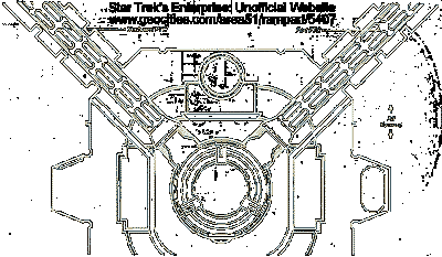
As the entire engine system undergoes start-up, the energetic plasma generated is split into two streams at nearly right angles to the ship's centerline. The power transfer conduits (PTC) are magnetically similar to the constrictor segments, in that they constrain the plasma to the center of each channel and peristaltically force the plasma toward the warp engine nacelles, where the warp field coils (WFC) utilize the energy for propulsion.

Port and Starboard Warp Power Transfer Conduits

The PTC channels extend from Engineering aft, where they intercept the warp engine support pylons. Each channel is fabricated from six alternating layers of machined tritanium and transparent aluminum borosilicate, which are phase-transition welded to produce a single pressure-resitant structure. The interfaces with the reaction chamber are explosiv shear-plane joints that can separate within 0.08 seconds in the event the warp core must be jettisoned. The joint are set during manufacture and cannot be reused.

Taps for the electro plasma system (EPS) are located at three places along the PTC, at 5, 10, and 20 meters aft of the shear-plane joints. Taps for the EPS are available in three primary types, depending on their application. Type I accepts 0.1 capacity flow for high-energy systems. Type II accepts 0.01 input for experimental devices. Type III accepts relatively low-power input for energy conversion applications.

Top of the page

Copyright © 1998 Tan Ngo-Dang
Contact: tangowebmedia@sympatico.ca
URL: http://www.oocities.org/area51/rampart/5407/warp02.htm
Created on 02/26/98
Updated on 05/30/98
Page status: final