Installing Nology "Hot Wires" on a MR2
Detailed Instructions To Install The
Nology "Hot Wires" Spark Plug Wire Set
And Beru "Silverstone" Spark Plugs
On A 1993-1995 MR2
WARNING: before starting this work, please allow your engine to cool
it is not a good idea to be doing this work on a hot engine.
WARNING: Make sure you read all the way through these instructions
at least once before proceeding with the work.
TOOLS USED:
10mm 1/4 drive socket
12mm 3/8 drive socket (standard socket)
12mm 3/8 drive (deep socket)
5/8 3/8 drive spark plug socket (has internal rubber sleeve)
14 inch 1/4 drive extension
12 inch 3/8 drive (lock end) extension
6 inch 1/4 drive extension
18 inch 1/2 drive breaker bar (to break loose the spark plugs)
1/4->3/8 drive adaptor
3/8->1/4 drive adaptor
1/2->3/8 drive adaptor
0 to at least 25 ft/lb torque wrench
7/64 allen wrench (to install wire looms)
small pair of wire cutters
small pair of slip joint pliers
small wire brush
PARTS PURCHASED
Nology Hot Wire Set
Nology Hot Wire Separators
Beru "Silverstone" S3F Spark Plugs
OTHER PARTS PURCHASED:
2/0 Battery Cable 14 inches long
Flat spark plug indexing washers
OTHER PARTS AND PRODUCTS USED:
Qtips
Silicone grease
Wesleys Black Magic Silicone
Duct tape
320 grit (wet dry) sand paper
Griot's Garage Antisieze paste
several clean shop rags
two or three large clean bath towels
WHY A GOOD GROUND IS IMPORTANT:
It is important to explain why a good ground is very important
when installing the Nology Hot Wires.
Nology Hot Wires pulse the spark at 4 nano seconds and 1000 amps.
Because of this extremely high pulse current and high frequency, an
excellent "frame ground" is necessary. Also the specific characteristic
of the pulse, its frequency, must be taken into account.
As the frequency of the current goes up what happens is that the current
tends to flow towards the outside of the conductor, this is known in
electronics as the "skin effect". To give you an idea of what frequency
we are talking about, then consider the formula Freq = 1/Time.
So if we use this formula we see that Freq = 1/4 nano seconds and that
divides out to 250 megahertz. At that frequency the "skin effect" would
be very much in effect. So, the ground wire must have a very large surface area so that the
current will have a maximum amount of "skin" to move on.
That is why a 2/0 sized welding cable conductor is chosen. It has thousands
of smaller wires that add up to a very large surface or "skin" area for
the high frequency current pulse to travel on.
Also to take into account, since you will see in this installation, that
the most logical place to ground the Nology Hot Wires is on the
air intake connector, that is mounted on the throttle body.
One must look at the ground path from the air intake connector to the
real ground which is the negative terminal of the battery. If you take
a good look at the ground path you will see that there are several gaskets
in the path. Remember that we are talking about a high frequency pulse
current, so maximum "skin" area is very important. A gasket will block
that current. That is why running a heavy ground wire from frame ground
to the air intake connector is very important. This will provide the
shortest, most direct path to ground, and will allow a maximum amount of
conductor area or "skin" for the current to travel.
CONNECTING FRAME GROUND:
First lay down at least two of the large bath towels on the top surface
of the car around the engine, this is so you don't damage the paint, and
you also have some where to lay your tools out without scratching the
paint. Lay out the tools that you will be using, at least most
that are practical, that way it provides easy access and makes the job
go much smoother.
Before proceeding with this first step, you may want to mark the position
of the engine hood latch, this can be done by either marking with a scribe
or a marker of some kind.
Using a 12mm socket 3 inch extension and 3/8 drive ratchet, remove the
two bolts that hold down the engine lid latch. Lay it face down on top
of the intake manafold. Now using a small
knife or scraper, scrape the paint off around the hole so as to provide
a bare metal contact path. You should have the latch laying face down
and scraping the paint off around the back side holes. Scrape the paint
off around both holes on the back side of the latch. When this is done
use a small piece of the 320 grit wet dry sand paper and get any remaining
paint off so you have a clean surface. Now use the small wire brush and
brush around the hole. Now you are going to do the same to the holes on
the frame of the car where the latch mounts. Make sure that there is a
good bare metal contact area.
Now turn the latch over and on the (passengers side US) of the latch
assuming that you are standing of the passengers side (US), of the car
then scrape the paint off around the hole on the latch, this is where the
2/0 battery cable will be screwed down.
After you finish scraping the paint off, and you have a good bare metal
contact area, locate one of the latch bolts, and scrape the paint off the
inside surface of the washer using a small knife and then wire brush it.
Now for those that may be concerned with rust, then put a small dab of
silicone grease on each of the areas where the paint was scraped off.
This will provide a protection against water, but at the same time will
allow electrical contact. Now locate the 2/0 battery cable and using the
wire brush, brush around the end connector contact area, this will remove
any small amount of surface oxidation that might exist. Now locate the
latch bolt that you scraped the paint off the inside of the washer, and
position the latch, the 2/0 cable and the bolt, and screw it down in place
but not very tight yet. Now locate the other latch bolt and screw it down
in place, but not very tight yet. Now position the latch to match your
scribe marks, or just "eye ball" it, and then tighten down the bolts using
a torque wrench, 12mm socket, 3 inch extension. Make sure that the
2/0 battery cable is positioned horizontal to the lid surface, (see
picture for details). The torque spec is 12 ft. lbs.
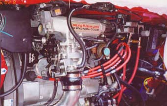
Now we are ready to anchor the other end of the 2/0 battery cable on the
top (passengers side US), bolt that holds on the air intake connector.
Using either a 12 mm openend box end wrench or
a 12mm socket and drive, loosen the bolt on the air intake connector.
If this is the first time you have done this, it will be a little hard to
break loose because of the corrosion. After removing the bolt, then using
the small wire brush, brush the bolt, and remove any corrosion that might
be built up on it. Also brush around the bolt hole on the air intake
connector, this will remove any surface corrosion or oxidation. Now using
a Qtip, and a small dab of silicone grease, dab a little grease on the
threads of the bolt, this will keep it from getting even more corroded.
Now using the small wire brush, brush both sides of the battery cable
connector. Now position the 2/0 battery cable,
and position the bolt back through the cable hole and then into the air
intake connector, and tighten down to 14 ft. lbs. using a 12mm socket
3 inch extension and torque wrench.
At this point check your work and make sure that all bolts are tight.
That completes the installation of the ground wire.
INSTALLING THE BERU SPARK PLUGS AND NOLOGY HOT WIRES:
First note on a piece of paper, how the spark plug wires are connected
to the distributor cap, this will give you a reference later when you are
ready to hook them back up.
After doing this then remove your stock wires and looms and set them
aside.
At this point blow out the spark plug wells, and the general
area around the valve cover so that there is no chance of dirt getting
down into the engine. If you have an air compressor this
is fairly easy, if not, you could use the reverse flow of a vacuum
cleaner or a shop vac of you have one.
Now using a 10mm socket 1/4 drive, 6 inch extension 1/4 drive, and 1/4
drive ratchet, remove the No. 1 air intake connector tube. Loosen the
3 inch hose clamp up next to the air intake connector, and then the
2 inch hose clamp back on the intercooler output. Now pull the 3 inch
hose off the air intake connector, and then pull the No. 1 air intake
tube off the hose on the intercooler. Then stuff a clean shop rag into
the intake air connector so you won't get any dirt in it.
Now assemble your 5/8, 3/8 drive spark plug socket, 12 inch 3/8 drive
extension, NOTE: use a locking end extension, if you don't have one
then you can use a piece of duct tape and tape the 5/8 drive socket to the
end of your extension, or it could pull off and be fun to fish out of the
spark plug well.
Use a breaker bar to break the plugs loose.
If you don't have to then use a 3/8 drive ratchet and break
loose the plugs and remove them.
On most cars, after changing the plugs out a few times, there tends to build
up some level of anti sieze compound at the bottom of the spark plug well
where the spark plug seats. Use compressed air to blow out any dirt that
might be in the spark plug well.
Now you are ready to install the Beru Silverstone spark plugs.
Since they come from the factory gapped at .031 or 0.8 mm
then if you have a turbo charged car, or even an NA car
I would recommend NOT regaping the plugs, the Nology Hot Wire
instructions recommends that you not gap them wider than .035
NOTE: If you are going to follow the indexing proceedure, then you may
have to cut off the washer that comes on the Beru spark plugs,
you may not need to do this, check the washer that comes with
the plug, and it may index up OK, with out having to change it.
This can easily be done by using a small pair of wire cutters and
grabing the edge of the washer and squeeze and at the same time
twist and break it in two. Then it is easy to pull off.
If you are not going to index your plugs then skip the indexing
step, and proceed to install your plugs with the stock washer
provided and torque them down.
WARNING: the Beru spark plugs use silver for the center electrode.
This makes the electrode very soft, and easy to bend.
It is not recommend to use a spark plug gapping tool that puts
pressure on the center electrode. The plier like "fancy"
gapping tools, rely on putting pressure on the center electrode
to bend the ground electrode into shape. This WILL NOT WORK
with the Beru plugs, all you will succeed in doing is smashing
the center electrode down.
If you must regap the Beru plugs, then use a
gapping tool that only moves or puts pressure on the ground
electrode.
INDEXING THE PLUGS:
First assemble your 5/8, 3/8 drive spark plug socket, and either locking
end extension, or tape the socket to the end of the extension. Now locate
one of the Beru spark plugs and insert it into the 5/8 drive socket.
Now cut a thin strip of duct tape and align it on the shaft of the
extension so that it lines up with the open gap of the plug.
Choose one of the indexing washers,
NOTE: DO NOT stack the indexing washers, use only ONE at a time.
slide the washer over the end of the spark plug, now using a small pair
of slip joint pliers, gently squeeze the ends of the washer so that it
won't slide off the spark plug and you have to fish it out, which is real
fun.
Locate your antiseize compound and apply a good amount to the threads of
the spark plug.
NOTE: for the sake of knowing which spark plug I am talking about, they are
numbered from drivers side (US), to passengers side (US),
or if you are standing directly in the rear of the car, from left
to right, #1, #2, #3, and #4.
NOTE: the #3 spark plug, the one just below the air intake connector
is a bit of a problem. Use a long 1/4 drive extension to insert and
remove this plug, that way you do not have to remove the air intake
connector. Along with this, also use two adaptors, a 1/4 -> 3/8
adaptor, and a 3/8 -> 1/4 adaptor so you can use a larger 3/8 drive
ratchet with the extension. Do NOT try to use a 3/8 extension
to insert or remove the spark plug from #3 hole, as you will cause
the plug to bind against the threads and could damage the threads.
Now screw this plug down into #1 spark plug hole, and using your torque
wrench set to 10 ft. lbs. tighten it down. Now observe where the piece
of duct tape is on the extension shaft. If it is in a perfect position
then it would be pointing directly towards the rear of the car. Or if
you drew a line directly down the center of your car from front to back
this would be a center line. The ideal position would be if the tape
on the extension were pointing exactly south, north being the front of the
car. It would still be OK even if the position were within a 30 degree
arc either side of the center line.
The idea being that you want the open gap of the spark plug exposed to the
intake charge. On the MR2 1993-> that is from about 30 degrees either
side of a center line dividing the cylinder in half from north to south
south being the side where the two intake valves are, ie.(rear of the car).
If the indexing washer did not allow the plug to position correctly then
remove the plug, squeeze the opposite sides of the indexing washer so
you can easily remove it from the spark plug, and choose one of the other
indexing washers, either thicker or thinner.
NOTE: you may want to read any instructions that might have come with
your washer set, they usually tell you how many degrees each of the
washers will shift the position of the plug. This may or may not
help you decide which one to use next.
Keep doing this process of trial and error until you find one of the three
sizes that will position the spark plug at or very near the optimum
position. If none of the washers will position the spark plug at or near
the optimum position then you may have to sand one of the washers down
using some wet dry sand paper and a little elbow grease.
Keep going at this proceedure for each of the four plugs until they are
all seated.
BLOW BY AND HOW IT CAN BE SOLVED:
Now before you do a final torque on the spark plugs, there is possibility of blow by.
At higher boost levels, above stock, you may
run into a problem where the spark plug, torqued down to the stock torque
of 13 ft. lbs. will not be sufficient to hold in all of the combustion
pressure, and some of the pressure will blow by the spark plug. Some
have reported sufficient blow by to cause the spark plug wire boot to be
blown off the plug and completely out of the spark plug well.
Torque the plugs down to 20 to 22 ft. lbs of torque
to prevent blow by.
After having seated all of the spark plugs, and indexed all of them you
want to do a final torque of the plugs. Set your torque wrench to the
setting you want to use and torque them down.
INSTALLING THE NOLOGY WIRES:
Now you are ready to install the Nology spark plug wires.
Hold all four wires in your hands with the large boots at top, even them
up so you can tell length, and locate the shortest wire first.
Using a Q-tip and a small dab of silicone grease, insert the grease into
the spark plug end of the boot. Spread it around inside. This will keep
the boots from heat welding themselves to the spark plug porcelain
insulator. Now press the shortest wire spark plug boot into the #1
spark plug well, and make sure it seats OK, you should hear a slight
click as it sets onto the center electrode top of the plug.
Now you will want to use a Q-tip and a little
Wesleys Black Magic Silicone and put it on the distributor end of the
connector TOP, as you hold the distributor
plug in your hand, you will see that there is an outer hard plastic
connector clip mechanism, which is used to hold the plug wire down on the
distributor cap. Slide this up as far as possible, and observe the top
black silicone rubber part of the plug boot. You will see that this part
when in place, will be pushed up through the hard plastic outer clip.
This fit can be extremely tight, so you may need to put
a little of the Wesleys Black Magic Silicone on the top part of the
black plug boot. This will allow it to slide
through the top of the hard plastic outer clip and down to lock in place
on the distributor cap.
Follow this same proceedure for the remaining three plug wires. Using
the notes that you made previously to ensure that the wires are being
hooked up correctly and going to the proper position on the distributor
cap. Make sure that the hard plastic outer shell actually clicks down
in place on the distributor cap. Check this and make sure they are
locked in place.
HOOKING UP THE NOLOGY GROUND WIRES:
The #1 and #2 spark plug grounding wires are going to go on the
drivers side (US), of the air intake connector. #1 going to the bottom
bolt, and #2 plug ground wire going to the top bolt.
NOTE: ONLY remove ONE BOLT OR NUT at a time from the air intake connector.
Starting with #1 spark plug grounding wire. Using a 12mm deep socket
3 inch extension and 3/8 drive ratchet, or if you choose, a 12mm box end
wrench break loose the bottom nut from the air intake connector.
Locate your small wire brush and brush the stud around the area where the
nut was, and brush the nut also. Brush the face area around the stud
on the air intake connector. Now using a Q-tip and a small dab of
silicone grease spread a little around the threads of the stud. Now brush
the ground wire connector on both sides. Slide the ground wire connector
onto the air intake connector bottom stud and screw the nut down, then
using a 12mm deep socket 3 inch extension, and torque wrench set to 14 ft.
lbs. torque the nut down to spec.
Proceed to do the #2 Nology ground wire in the same manner on the top
stud (drivers side US), of the air intake connector.
Now you are ready to connect the #3 and #4 Nology ground wires. These
will be going to ground on the accelerator cable bracket.
NOTE: again only remove one bolt from the accelerator cable bracket at a
time.
#3 Nology ground wire will be going to the right side bolt and #4 to the
left side bolt. Using either a 12mm box end wrench, or a 12mm socket and
drive, loosen the right accelerator cable bracket bolt. Using a small
wire brush, clean the corrosion off the bolt, and also brush the face of
the bolt hole. Apply a little dab of silicone grease to the threads of
the bolt, and also brush the connector end of the ground wire.
Position the #3 ground wire connector in place and put the bolt through
and screw the bolt in place, and using either a 12mm box end wrench or
a 12mm socket and drive, tighten down the bolt.
Now follow the same proceedure for #4 Nology ground wire and bolt it down
in place.
Go back over your work at this point, making sure that all of the
connections to the distributor cap are correct, and that all bolts and
nuts are torqued down to spec. Check for anything out of place or
missing. Check pictures for details.
If you also purchased the Nology wire looms you will want to place them
on the wires at this time. You will need a small allen
wrench to do this.
Now do a little clean up, put away all of your tools, and make sure that
your not missing any, or that any tools did not fall down into the
engine compartment.
Try starting up your engine now, and be prepaired to enjoy your new
Nology "Hot Wires."
OBSERVATIONS BY MARC SUMMNERS:
"I have a Jacobs Omni Pak, and with that had Jacobs energy core wires
rated at 200 ohms per foot. For spark plugs, I had Autolite 3934's
these are the NON-resistor plugs".
OBSERVATIONS OF THE CARS PREVIOUS PERFORMANCE:
"With the Jacobs wires and
Autolite plugs, at 15 psi. of boost, I was not able to get the ignition
to fire reliably when the spark plugs were gapped at .030 and just able
to get it to fire reliably when the spark plugs were gapped at .028
Also when at idle after driving 16 miles from work, I let the car idle
for a few minutes before shuting it off. After doing this for some time
one tends to listen to the engine, and knows the sounds. The idle with
the Jacobs wires and Autolite plugs was jerky. It would constantly miss
or skip a beat. Of course the engine would jerk when this would happen."
OBSERVATIONS OF THE CARS CURRENT PERFORMANCE WITH THE NOLOGY HOT WIRES:
"I still have the Jacobs Omni Pak ignition system."
"The first thing I noticed was the idle, it is now smooth, not even one
beat missed, and rock solid. This was very easy to notice since I was so
used to hearing it before."
"The next thing I noticed was the full boost performance. The Beru plugs
as I received them from,
were re-gapped to .030.
Never before now had I been able to get the previous setup with the
Jacobs energy core wires to fire consistently at 15 psi of boost
with the plugs gapped at greater than .028
NOW with the Nology wires and the Beru spark plugs gapped at .030 the
engine doesn't miss a beat, NOT EVEN ONE at full boost 15 psi, in 3rd
4th or even 5th gear!"
"I have since used plugs gapped at .031 with the same excellent
results."
"Another very important issue is as had been reported with earlier versions
of the Nology wires, that they were causing problems with the ECU.
I can report that now, such is NOT the case.
I noticed no additional static or RF noise from the Nology wires and no
weird behavior from my ECU at all."
"In all, I am very impressed with my current performance with the
Nology wires and Autolite 3934 spark plugs. Significant, observable, results."
 Back to Tech Page