
Next job is to clean up and prepare the subframe. I decide a coat of silver Hammerite will leave it looking decent. I have to grind some of the web off the sides of the pivot mounting, and grind some off the locating tubes. I also decide to modify the handbrake cable whilst I can see what I am doing, which proves surprisingly easy, even though I can't see the purpose of some of the changes. Leave the end unfinished as I can't fix the length until it is in position and the handbrake is fitted. Surprising how many things are inter-related, it makes it hard to plan the work in advance.
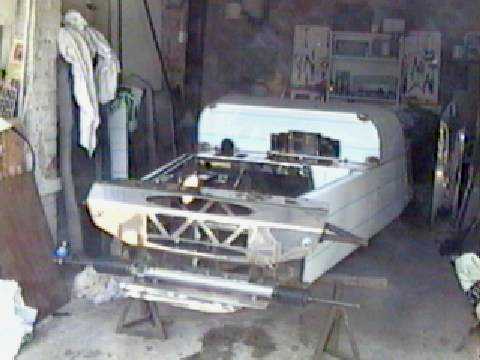
Now to fit the back subframe - another nightmare. Having ground the webs completely off the sides of the pivot mounting ("you might need to grind these down a little", according to the video), it still won't fit in without some brute force, and with one of the locating tubes at an angle. Measure it up and the subframe is about 2 cm offset to the body, which is hardly surprising when I look at the holes for the pivot arm - there is about 2 cms. more metal between the hole and the edge of the body on one side. Back to the grinder. Finally get it in to what looks like a relatively unstressed position, with about 1 cm offset which I think will be OK, but now I want to measure to check the alignment front to back ( I am getting suspicious now).
Subframe alignment seems OK now, so I just have to drill the 12 mm hole into the subframe to bolt it into position. This goes into a box section in the subframe, so I will have to cut a hole on the other side to put the nut on. Decide to do it properly, and buy a hole cutter. This makes surprisingly short work of the metal, but then another problem. I have cut the hole in the only position available, next to the rubber mounting. Turns out that the bolt is coming through over the top of the rubber mounting, and I can't get a spanner through the hole onto the nut. After much struggling, invest in a cheap combination spanner which with the aid of a blowtorch and big hammer can be adapted to fit. I hadn't realised before I started how important a big hammer was going to be for this build!
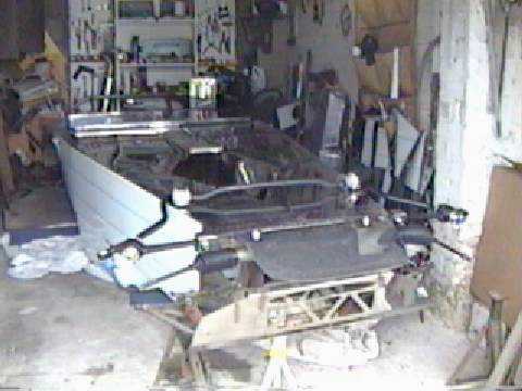
Front suspension is quite straightforward - I decided to get new hubs which would take the ventilated discs from the scrapyard (lesson - don't just take the tools you will need, take EVERYTHING to the scrapyard). These fit with no problem, and a spot of Meths cleans the protective coating off the discs (wonder how many people forget to get this off - presumably it would burn off eventually, but stopping might be interesting until it did!). leave evrything finger tight until I get the engine in and the suspension in a more or less normal position. Next problem is the rear suspension. I have the "new" rear springs which are shorter than the previous ones, and so the top brackets have a box section welded on. This isn't a problem in itself, except that it limits how far out you can mount the top of the spring. The real problem is that the bottom bolt is 12mm rather than 10mm, so it doesn't fit the subframe or the spacers. Advice from Richard Stewart at Robin Hood - "drill out the subframe, and we will send out new spacers with the bits pack coming with the additional video" (what bits pack, what video?). "Don't know when it will be ready, but just fit them without spacers for now"! The mounting brackets go on ok, but because of the box section the top mounting has to fit into, I have virtually no latitude to move the hole, and when I try to bolt the back of the bracket up to the body, it won't - the radius of the coil spring is greater than the mounting hole to body distance. Consider using spacers between the bracket and body, but I decide that this will weaken the construction considerably so I will talk to Richard Stewart at Robin Hood. We agree that I will return the brackets to him to have the box section rewelded with an offset to give more clearance. This is something of a blow as I am limited by not having the engine in, and I can't fit the engine without having the car mobile.
I decide that fitting the petrol tank is a self contained job that I can do now - it will get another bulky item out of the way as well. I am slightly surprised that it comes about 3 cms. below the rear panel, but at least this is one item I can be fairly sure is right - there is NO other way it could fit. Make up some support straps and shape them to fit against the tank. Quick coat of the trusty Hammerite, and the fitting is pretty straightforward - the silver paint makes the brackets fairly unobtrusive. On checking the video I see the approved method is simply to bolt on flat strips and let the bolts bend them to shape - IMHO my way looks much better. The sender unit will not fit in the tank - pick up pipe is too long, but this is easily modified. Having shortened it, I suddenly realise that this limits the tank capacity since I won't be picking up from the bottom. By my calculation the tank holds about 32 litres, and every 1 cm of depth unavailable will reduce the capacity by about 2 litres - looks like a case for a bit of flexible pipe pushed on the end!

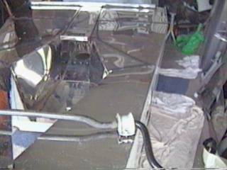
I decide that the procedure for using the later model engine mountings illustrated in the video is too much work, so get a pair of the older type from the scrapper. Wheel the car out, assemble my scaffolding frame, and hook the hoist onto the engine. Matthew starts pulling the rope and the trolley wheels start to become vertical again, when Matthew says he can't get it any further. Heartened by the thought that there are some advantages to my greater weight, I start to help. It still won't move. It begins to dawn on me that there is something wrong. Inspecting the top pulley, the rope has come off one of the wheels, and our combined efforts have jammed it very firmly between the wheel and bracket. No chance of freeing it under load, so have to lever some bits of wood under the sump, and take the pulley apart. With the rope on the wheels, the engine goes into the car comparatively easily (although the gearbox deposits some more oil on the drive). However, after much levering about of the engine and mounting sleds I can't get the engine lined up with both mountings at once. I decide the easiest approach will be to put the mounting onto the engine and lower the mounting onto the sled. This was the point at which I discovered that the hole in the engine bracket was smaller than the bolt in the engine mounting. Quick trip to the scrapper for new engine brackets reveals that not only is the hole a different size, the brackets are a different length, which explains why I was having so much difficulty. Engine drops in a treat after that.
Can't see how the gearbox mounting fits, however email to a fellow builder reveals that I need to move the rubber from the bracket and just use that (may sound obvious, but since it is riveted to the bracket it didn't occur to me). There are lots of advantages to following someone else! Lining up the engine is time consuming, but not particularly difficult once I establish where the centre line of the engine is. To my surprise and delight, the sleds don't interfere with the anti-roll bar fittings significantly (at least not after a bit of adjustment of the sled position). Now with just some plumbing and wiring the car could be driven!