C-119 Radios and Props
![]()
>All of the following information was written and contributed by
A/2c Charles LunsfordRadio Operator, 12th Squadron.
C-119 Radios and Props
![]()
>All of the following information was written and contributed by
A/2c Charles LunsfordRadio Operator, 12th Squadron.
The Fairchild C-119 was the last U.S.
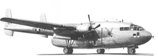 Air Force aircraft contracted for to be delivered with a Morse radio/telegraph key as standard equipment, and also the last have a station solely for a Radio Operator. Later aircraft have carried radio operators and had Morse keys added, but they were modifications - not built into the airplane.
C-119 was developed from the C-82, and the first C-119 was called XC-82A. C-119s were modified and modified again, and then modified some more, so it’s difficult to keep track of which modification had what radio and navigation equipment. Only a few “B” models were built and they were converted to “C” models early on. Most of the C-119s were built as “C” models, and converted to “CF” models, and then some of the CF models were converted to Gs. Only the group with tail number beginning with 53-78- - were built strictly as G models. I know exactly what the “G” models carried, because that’s the one I flew. The information on the B, C, and CF models is mostly from research.

Standard Hand Key
An automatic key has a long rod with an adjustable weight that bounces against a spring, sending the dots very fast. Pressed the opposite way against a regular spring, it sends the dashes. One doesn’t pound up and down on a bug—one caresses it from side to side. A really fast operator can set that weight bouncing so fast it chirps like a cricket—hence the name "bug."

The Bug Key
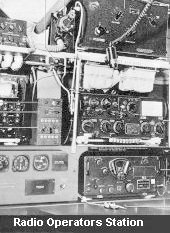
There were three categories of communicating radios. Liaison, Command, and Navigational aids.
LiaisonHigh Frequency long distance radios from 2 Megacycles to 25 Megacycles, used mostly for Air Traffic Control. C-119 B, C and CF models, always carried the AN/ARC-8, consisting of the old faithful BC-348 receiver which was used in concert with or ART-13A (T-47) Transmitter. Some aircraft carried a Collins 18S-4, with 20 pre-set frequencies. All HF installations were, of course, both voice and Carrier Wave (Morse Code) capable. Early C-119s carried a frequency meter for use in loading frequencies into the transmitters, and they also carried an antenna-loading unit used to energize the 66-foot antenna carried by all C-119s. In the C-119G, the Collins 618S-1 HF set was a combined transmitter/receiver and it was so advanced that about all that was necessary was to turn it on and off. No antenna loading was necessary.
The radio did it automatically. With 90 watts of power, and pre-set crystal frequency resonance, nothing that flew had more power. It was the first single sideband HF set installed in the C-119, and the beginning of the end for Radio Operators. It was so simple, even a student copilot could operate it and the small control panel for the 618S-1 was on the pedestal between the pilots.
Command
Very High Frequency and Ultra High Frequency sets used mostly by the pilots for communication with the control tower, approach control and other aircraft. These transmitted line of sight, so distance was limited.
 All C-119s carried the old AN/ARC-3 VHF set as the primary command radio. The frequency range was from 100 to 156 Megacycles, and it consisted of a transmitter and receivers. There were 8 present channels, however, those could be expanded by changing the removable crystals in the transmitter and recycling the receiver. The Radio Operator was responsible for a large box full of transmitter crystals, which were made of black Bakelite and not marked with the frequency, and were delicate. One of the least favorite things was to drop one of them in the cockpit on a dark night.
If one could find it, it probably wouldn’t work after being dropped. The ARC-3s were very old and the frequency cycling mechanism in the receivers would frequently stick. The Tech. Manual comically recommended a “sharp rap” to free the mechanism - and it worked, too! Every Radio Operator-to a man-hated the ARC-3. The other Command set carried by the C-119 was the AN/ARC-27 UHF transmitter/receiver, covering the wavelengths from 225 to 399.9 Megacycles. We almost never used it because only American Military installations had UHF capability, most of which was reserved for fighter and tactical aircraft. Like the Collins HF set, it was much more sophisticated than the other command set. It was pressurized for high altitude, and it had 1750 frequency channels. It also had a second built in receiver that was always tuned to the UHF Emergency frequency of 243.0, and was instrumental in saving this Radio Operators skin one dark night on a Ground Controlled Approach.
All of these radio set were made available to each crew station through the jack boxes of the AN/AIC-8 Interphone system on the early C-119s, and the AN/AIC-10 on the CF and G models. Hand-held microphone were at each station, however G models were equipped with microphone headsets, and although they still hung at ever crew station, they were never used.
Navigational Aids
All C-119 aircraft were equipped with the ancient and beloved AN/ARC-6 Radio Compass receiver. Of all the navigational aids, the ARC-6 was used the most often. Most aircraft had dual installation-two of them, and these Automatic Direction Finders were the mainstay of all Navigation in all C-119 aircraft. They had an old-fashioned crank to tune in the frequency and a flickering lighted (white) dial, right out of the 1930s. They operated in the Low Frequency range, from 100 to 1750 Kilocycles, which included the AM Broadcast band, and not only could you home the local radio station, you could listen to the music or the news.
 Each had its own loop antenna that homed automatically or could be operated manually, and operated a large round instrument with a big needle and a magnetic compass card located in the center of the top of the pilots instrument panel-far and away the largest instrument there. The ARC-6 received signals from the old Adcock Range Beacons, which transmitted crossed beams with “A” and “N” quadrants, and when I was flying in Europe, that’s about all that was available. It had a wire antenna of about 15 feet, mounted on the underside of the fuselage on early aircraft, and on the top of the fuselage on the G model. Adcock Range Beacons also required an AN/ARN-12 Marker Beacon receiver, which turned on a blinking light when the aircraft was over the center of the beacon. Later C-119s had an AN/ARN-14 Omni Range receiver, but again, as there was only one Omni beacon on the continent, it was almost never used. The same applied to the AN/ARN-18 Glidepath Approach Receiver - we could receive, but nobody had a transmitter. Most C-119s from the C model on, were equipped with AN/APX-6, -6A or the newer -25 IFF (Identification - Friend or Foe) Transponder. Early frequencies in these sets were classified and the Radio Operator had to carry the set with him if no military guard facilities were available.
Some C-119s also carried an AN/APN-12 Radar that could be, but never was as far as I know, used for locating a beacon on the ground for troop drops, or for identifying other aircraft. It would have been the duty of a navigator to operate, and a navigator was another navigational aid we almost never carried. Shortly before I left the Air Force in 1959, our aircraft were equipped with a TACAN (Tactical Air Navigation) set that I think was a Transponder. I have no idea of the nomenclature, but I recall when one homed a TACAN beacon, a little window in the instrument told you the miles from the station.
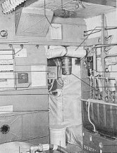
Last, but not least, every C-119 carried large 8 man life rafts that were equipped with an AN/CRT-3, Emergency (Dinghy) Radio Set - known as the “Gibson Girl” because of its shape. Held between the legs, it was hand cranked and sent out a Modulated Carrier Wave signal on both International Distress Frequencies of 500 and 8364 Kilocycles. We knew the Gibson Girl was there, but as with the parachutes we always wore, the very last thing we ever wanted to do was use it.
Editors note:
Thanks Chuck for this outstanding information about our radios.
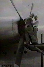
Note
The A644FN-C1 propeller still installed on some C-119G airplanes is basically the same
 as the C2 model except that a fixed mechanical low pitch stop has been installed which renders the reversing feature inoperative. The C1 propeller configuration may be readily identified by the exposed accumulator attached to the propeller hub (C2 propeller hub has a metal spinner-type cover) or by the type of throttle reverse stops found on the control quadrant. Refer to Throttle Reverse Stops, Section I. A mechanical low pitch stop is a permanent feature on the C2 propeller and is retracted electrically whenever reverse thrust is used.
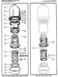
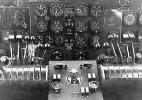
Propeller forward thrust operation is controlled by the propeller levers on the control quadrant, each of which is mechanically linked by cable and teleflex rigging to a control ring on its associated regulator. When a lever is placed full forward in the propeller governing range, the propeller blades assume a low pitch-high rpm position. As the lever is returned to some position in the propeller governing range, the propeller blade angle is determined by the lever setting and the power at which the engine is operating. The high pitch limit of the forward thrust governing range is fixed by a detent which engages a safety latch on each control lever.
SYNCHRONIZATION
Synchronization of the propellers is accomplished by manual setting of the propeller levers in conjunction with the tachometers on the instrument panel. Further adjustment of the propellers to eliminate noise beat must be done aurally. When the propeller levers are placed full forward, both engine speeds are aligned to the same settings, the levers at this maximum rpm setting will only set the speed of the engine within a few rpms of each other. This slight difference is enough to cause propeller noise beats normally referred to as “out-of-Synchronization.”
FEATHERING
Either propeller is feathered by releasing the safety latch on its associated control lever and moving the lever to the full extent of its rearward travel.
 This mechanically positions the valves of the governor assembly in the propeller regulator and allows propeller oil pump pressure to drive the blades toward the feathered position. As engine rpm decreases, accumulator pressure is automatically admitted to the system and completes the feathering operation in approximately 7-9 seconds, depending upon the blade angle before feathering. Unfeathering is accomplished by returning the lever to the INCREASE RPM position momentarily, then back to the midpoint of the governing range. This resets the governor for normal governing action and trips the feathering valve, again admitting accumulator pressure to the system to start the blades out of the feathered position. As the propeller begins to windmill, the pumps again become effective and drive the blades to the governed blade angle. When normal rpm is attained, governing action is resumed, the feathering valve is reset, and the accumulator is immediately refilled with oil.
REVERSING (C2 Propellers Only)
Reverse thrust for braking the landing roll of the airplane is obtained by lifting the pilot’s throttles and moving them rearward beyond the CLOSED or idling position.
Note
Approximately 50 pounds of force may be required to move the throttles rearward after clearing the idle stops.Lifting the throttles not only causes the quadrant reverse stops to retract by also energized the propeller reversing  coils which release the positive electro-mechanical low pitch stops on the propeller master gear assemblies. As the pilot’s throttles are moved into the REVERSE THRUST range, the interconnecting linkage in the engine throttle control system positions the negative thrust control ring at the propeller regulator which results in the constant blade angle of - 15.5 degrees. Further rearward movement of the throttles advances engine power and reverse thrust. The propeller, however, does not govern in reverse pitch and engine speed is manually controlled by positioning the throttles for desire engine power. The maximum obtainable engine power for reverse thrust is approximately 80% of METO Power. Unreversing is accomplished by returning the throttles to a position in the forward thrust range.
Two propeller levers, one for each propeller, are installed on the center of the control quadrant and provide the means for controlling the propeller in forward thrust and feathering. Each lever has an INCREASE RPM position (forward), and a DECREASE RPM position (aft), and a FEATHER position (extreme aft). A spring-loaded safety catch is incorporated in each control lever which engages a detent at the high pitch-low rpm end of the propeller range. This catch prevents inadvertent movement of the propeller levers into the FEATHER position.