| Introduction to Binary Space Partition Trees |
Introduction
Binary Space Partition (BSP) trees are handy for drawing 3D scenes where the positions of objects are fixed and the user's viewing coordinate changes (flight simulators being a classic example).
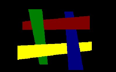
BSP trees are an extension of the painter's algorithmpainters_algorithm. The painter's algorithm works by drawing all the polygons (or texture maps) in a scene in back-to-front order, so that polygons in the background are drawn first, and polygons in the foreground are drawn over them. The "classic" painter's algorithm does have a few problems however:

Figure 1 - Cyclic Overlap
In this case it doesn't matter which order you draw the polygons it still won't look right!
BSP trees help solve all these problems.
How a BSP Tree Works
In order to understand how a BSP tree works it would be helpful to read the Win95GPE articles on basic 2D math and binary trees. As their name implies, binary space partition trees insert all objects into a binary tree, and each object partitions (or splits) space.
I'll start by explaining how a 2D BSP tree works. This kind of tree is used to speed up rendering in iD’s DOOM, even though the game itself is 3D. Once the basic 2D case is understood it is easy enough to extend it to higher dimensions (later I'll show how to incorporate time as a 4th dimension in order to get an apparently dynamic BSP tree).
Let's imagine we live in a 2D world and we have a scene like this:
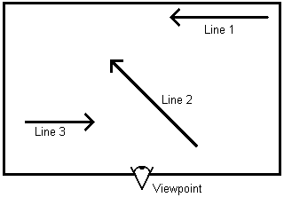
Figure 2 - An Example 2D World (assume viewpoint is the origin)
If we were to draw this scene using the painters algorithm we would draw line 1 first, then line 2, and finally line 3. Using BSP trees we can figure out the order beforehand and create a tree. First we note that any arbitrary point <x,y> can be on either side of the line or exactly on it (which can be regarded as being on either of the sides). When we build our tree, we take a line and put all the lines on one side of it to the left and all the nodes on the other side on the right. So for the above example we could wind up with the tree in Figure 3.

Figure 3 - A Possible Binary Space Partition
Tree For The Example World
Notice how line 2 is the left child of node 1, indicating that all it's points (as well as it's children’s) are on the left of line 1. Similarly line 3 is on the left on line 2.
However, if we use line 2 as the head node then we get the tree in figure 4.

Figure 4 - An Alternative Binary Space Partition
Tree For The Example World
Line 2 is the head node, line 3 is entirely on the left of line 2 and line 1 is entirely on the right.
But what we take line 3 as the head node? Line 2 doesn't fall entirely to the left or right. In cases like this we must split line 2 into two lines so that each portion falls nice and neatly onto either side of line 3. Figure 5 shows the same world with line 2 split into two smaller lines.
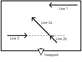
Figure 5 - Partitioning a Line
Note that the union of line 2a and 2b make up the original line 2. If the rendering algorithm draws each line correctly then the two line segments will appear as a single line on the screen. With line 2 now split we can generate a correct tree as shown in Figure 6.
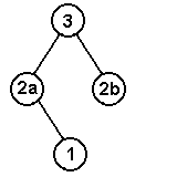
Figure 6 - A Tree for the World in Figure 5
The lines 2a and 2b are portions of the original line 2. If you draw both of them on the screen it will look as though you've drawn the entire original line.
Clearly the trick to creating good binary trees is to minimize the number of splits which occur while building the tree. In general you don't have to worry about balancing a BSP tree, since you have to traverse every node in it every time you draw the scene anyway (although, as you'll see later on, there are optimization tricks which make this no longer the case). The trick is to figure out how to organize the tree so that you get the least number of polygon splits. I tackled this by looking at each polygon yet to be inserted into the tree, calculating how many splits it will cause if it is inserted next and selecting the one which will cause the fewest. This is a very slow way of going about things, O(N^2) I think, but for most games you only need to sort the tree once when you are developing the game and not during the game itself.
Extending these concepts to 3D is pretty straight-forward. Let's say that polygon 1 is at the top of the BSP tree and we want to insert polygon 2. If all the points in polygon 2 fall on one side or the other of polygon 1 then you insert it into polygon 2's left or right node. If some points fall on one side and the rest fall on the other, then you have to figure out the line of intersection formed by the planes that each polygon lies in and split polygon 2 along this line. Each of these 2 new polygons will then fall on either side of polygon 1.
To draw the objects in a BSP tree you start at the top node and figure out which side of the object your view coordinate is on. You then traverse the node for the *other* side, draw the current object, then traverse the node for the side the view coordinate is on.
Creating the Tree
This section is still being written. You use a weight function: k1*abs(npp-nps)+k2*npc
where npp = positive polys
npn = negative polys
npc = split polys
nps = same plane polys
Optimizing The Tree
So far I've given the basic algorithm for generating and using BSP trees. BSP trees are extremely fast compared to other sorting methods, but even they can be sped up even further. Consider the demo world in Figure 7.
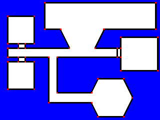
Figure 7 - An Example 2D World
At first glance we can see that there are a total of 51 lwall segments (each wall segment is bounded by red vertices on the map). To render the image we need to create a BSP tree and traverse it by popping the view position <x,y> into each line's equation, side = a*x+b*y+c. The sign of side will tell us whether the line is visible (for backface cullingback_face_culling) as well as which sub-tree we need to traverse first. In the 2D case this would require a total of 102 multiplications and 102 additions.
However, when we look closely at the world we can see that there are in fact only 4 unique line directions: horizontal, vertical and two diagonal directions. (Actually I lie, there are really 8 unique directions, since each wall can point in either direction along each line. But careful design of our data structures can take care of this for us). Any walls pointing in the same direction will have the same a and b values in their line equation. Walls which fall on the same line (such as all horizontal walls in the main middle corridor) will also have the same c value.
By taking advantage of this redundancy we can greatly reduce the amount of work required to traverse the tree. Using this method we would only need to do 8 multiplications and 55 additions. If we also take into account the lines which have the same c value then we can reduce it further to 8 multiplications and 31 additions.
This method also lends itself very nicely to the 3D case. Surfaces with the same orientation will have identical normals (once again, pointing in one of two possible directions), while surfaces in the same plane will also have the same k value.
Copyright (c) 1997 Mark Feldman (pcgpe@oocities.com) - All Rights Reserved
This article is part of The Win95 Game Programmer's Encyclopedia
Please retain this footer if you distribute this file.