| Portal Engines |
Introduction
I remember reading somewhere that Descent used a method known as "connected cubes" to do hidden-surface determination. Although Descent doesn't really use "cubes" as such, it does use six-sided structures that can be deformed into any shape, provided they remain convex. Building a world out of these "cubes" is somewhat restrictive, but the general principle can be extended to more complex shapes which give the game designer more freedom in the type of worlds that can be represented. Engines which use this technique are commonly referred to as "portal" engines, for reasons that will become apparent later in this article. When combined with Binary Space Partition Trees, portals provide a fast and powerful way of rendering complex scenery.
Basic Description
In this section I'll show the basic principle behind the portals method in 2D. Later I'll show how this can be extended to the slightly more complex 3D case.
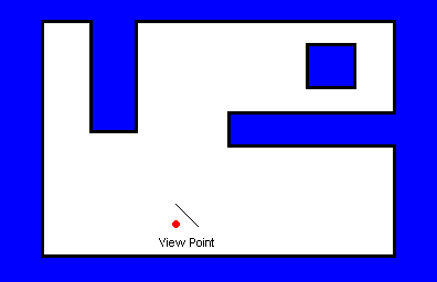
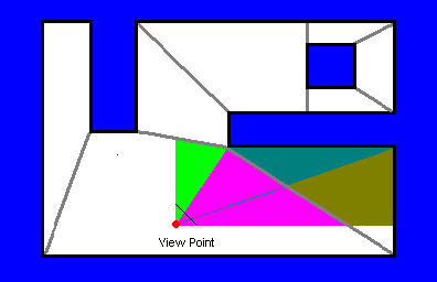
Consider the world shown in Figure 1.
Figure 1 - A Typical 2D Scene
The red dot represents the view point, the short black line next to it represents the projection plane, i.e. the user is looking north-east.
The first step is to partition this world up into a collection of smaller 2D polygons. Each polygon must adhere to the following requirements:
1) It must be convex in shape.
2) Each side of each polyhedron must be either mapped with a texture or connected to a neighboring polyhedron (i.e. an invisible portal).
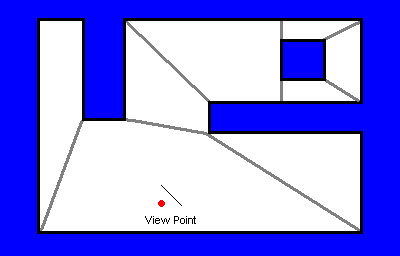
Figure 2 shows one way we might choose to do this. (The exact details of how this is accomplished will be discussed later).
Figure 2
This world has been divided up into 8 smaller polygons, and each one adheres to the requirements outlined above. Note that each side bounding a polygon is either a solid "wall" or an invisible "portal".
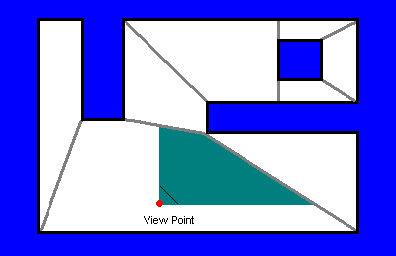
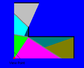
To render this scene we must first determine which parts of the world are visible from the viewpoint. Figure 3 shows this area for the polygon the view is in.
Figure 3
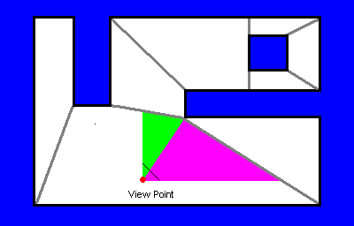
The trick is to cycle through all the edges in the current polygon, determine which portion of each edge is visible, and render the appropriate image. In figure 3 we can see that the view window has intersected with 2 edges in the current cube, so this would result in 2 new "windows" with which to render. Figure 4 shows these two windows color-coded. Note that each window contains one (and only one) edge, although only a portion of the edge may actually be inside the window.
Figure 4
Let's now turn our attention to the purple window. This window intersects one of the portals created when the world was split up into polygons. This portal effectively gives us a "window" if you like into the neighbouring polygon. If there had been a real wall there then we could simply render the visible portion. This is a portal though, so we must now render the polygon on the other side of the edge using the purple "window" as our new clipping window. This is how the portal method achieves hidden surface removal.
Figure 5 shows the two new windows generated in the next cube.
Figure 5
In Figure 5 I've drawn a thin line through the middle of the purple window. This is simply for illustrative purposes to show how the dividing line in the neighbouring polygon relates to the view point. The purple window itself is not split.
The two new windows each intersect with an actual wall object, so each of these wall portions can be drawn. We then return and repeat the entire process on the original green window. Figure 6 shows the final room with each of the resulting windows highlited. Portions of the world which are not visible to the viewer are not shown.
Figure 6
Looking at the final figure we can see that a total of 7 "clipped areas" were calculated. 4 of them contained wall objects to be rendered, the remaining 3 were "empty" and can be considered an expense of hidden-surface removal.
The 4 windows with walls however contain the exact clipping information needed to render the wall objects to the screen. In general rendering texture mapped surfaces is slow, so it's much faster to generate clipping windows like this (including empty ones) rather than draw overlapping wall objects. Furthermore, the starting window represents the visible area on the screen, so the polygons are already clipped to the screen area when it is time to render them.
But Don't Some Polygons Get Drawn Twice?
Yes! It's perfectly possible (and probable) that several windows can arrive at the same polygon, thus causing it to be drawn twice or more. The windows however will not be overlapping, so different portions of the polygon will be rendered in each. If speed is of essence then it's a good idea to keep track of polygons which have been visited so you can avoid many of the calculations the second time round (at the expense of memory and the extra programming required).
Special Effects
The beauty of this technique is it's simplicity, and this is particularly evident when it comes time to implement special effects.
Glass, for example, is perhaps one of the simplest effects to implement. Let's assume that during rendering a view volume intersects with a window. If it were a normal wall then we would perform the clip and use it to render the appropriate texture. With a window however, we can treat it as though it were a portal, render all objects on the other side, then come back and render the glass effect over top using the same view volume. There are probably numerous ways of rendering glass effects, a transparency map is the one I use. (I once tried simply darkening all objects rendered on the opposite side of the portal, however this gave unsatisfactory results).
If a view volume intersects a glass object then we would typically render all objects on the other side of it before applying the transparency map. However, if we first apply the mirror matrix to flip all objects about the plane that the "glass" defines then we'll have a mirror with very little extra processing overhead. In this way, the view volume effectively bounces back into the current polygon instead of passing into the next. In practice I've found that there are a few extra things you have to worry about: all surface normals are flipped, vertex ordering is reversed, you have to make a slight modification to the texture mapping routine to also render back-to-front, and so on. I solved all problems by simply maintaining a variable, inmirror (which keeps track of whether the current view volume has been mirrored or not) and whenever a mirror object is encountered this boolean variable is toggled. Using this technique I've managed to get very nice looking mirrors, I even constructed a "Hall of Mirrors" room once containing several of them all reflecting each other. And of course the rendering speed was the same as if the user were in a large room looking through many windows.
One of the advantages of representing a world with convex polyhedrons is that any given face can be partitioned into smaller faces. This can be used to reduce memory requirements and also makes it is very easy to implement hot-spots. Consider the following image of a stone wall with a large "push button" on it:

Figure 7
The wall itself could be part of a single polyhedron with several faces defined for it's surface:
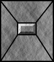
Figure 8
The button face itself could be tagged with a certain attribute so that the application knows. If the user presses it (eg with a mouse click) then the texture could also be changed to one showing the button in the pressed state. Techniques like this allows you to map many different types of surfaces without significantly increasing the memory required by the textures (the same texture map is used to render the outer 4 faces). Plus it still results in no pixel overlap.
Copyright (c) 1997 Mark Feldman (pcgpe@oocities.com) - All Rights Reserved
This article is part of The Win95 Game Programmer's Encyclopedia
Please retain this footer if you distribute this file.