The following is article is by Robert Biegler and was originally posted to the egroups.com proa file discussion list in mid-July 2000. Robert has previously experimented with a hapa-stabilized sailrig for a canoe - an article about his work can be found at the OCSG site.
See also Robert's Swingtacker design. Comments or queries can be directed to Robert.
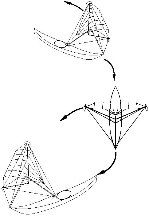
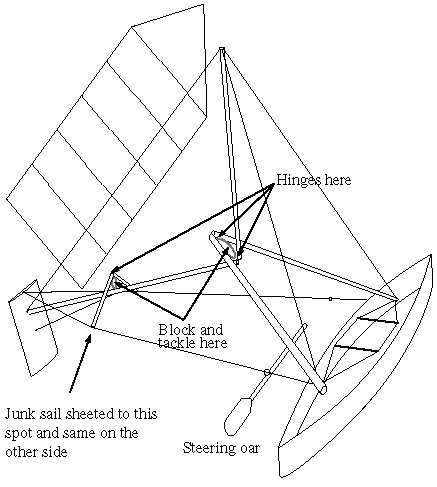
These are ideas how to adapt some of the ideas Bernard Smith described in "Sailloons and Fliptackers" for use on canoes and kayaks. Apart from putting the rigs on rather mundane hulls, there are two deviations from Smith’s designs: First, the sails have sheets, so they can be depowered without having to pay much attention to the boat’s heading. Second, there are only ever two of the compression members joined up by a hinge. These pairs of spars in turn are connected only by a simple block and tackle, which is itself only in tension. The whole rig can be folded up by releasing that line. Another line could run round the peripheral wires, to gather them all in (not shown here). If the fliptacker on the kayak could be folded up quickly and safely on the water, it would make a practical and non-heeling rig.

Both rigs transmit no heeling to the hull if the balance of forces is as follows: Imagine a vertical plane through the two points where the tetrahedral framework attaches to the hull. The resultant force from the sail and that from the foil should intersect this vertical plane at the same height. For the fliptacker that height would normally be the axis through the two attachment points, because the fliptacker's sail should be symmetrical.
In the case of the canoe rig, the resultant force from the sail could pass through the vertical plane higher or lower than the attachment axis. Angling the foil accordingly would still make the rig non-heeling. However, reefing would change the intersection point of the sail force. In that case, it would probably be best to allow some heeling with full sail, which would be taken up by an ama, and angle the foil so that the rig is non-heeling with a reefed sail. An alternative to the junk rig shown here would be a jib attached to a boom. The boom, in turn, would be pivoted from a point about 25% from the luff. The fully battened jib of the Hobie Cat 16 would be perfect for that.

The canoe rig does not flip, because I am not sure the rig would be light enough to make flipping easy enough for short tacking. This is supposed to be a cruising rig, so operation has to be easy. It will probably be necessary to add a small hull to the foil, just to support the weight of the rig at low speed. The three great attractions of this rig for a canoe are: there is no heeling; all sail and steering forces are contained within the rig while the hull only gets pulled along; the spars are fairly compact (2.6 m for 4 m between tips) and the rig should fold up and stow in the boat fairly easily (if a way can be found to gather in the wires and sail, that should even be possible on the water).
There is one thing I am not sure about. I tried to estimate the compression forces on the spars for a given sail force and allowing a certain sag of the wire from which the sail is suspended. For the canoe rig I assumed the tips of the spars would be 4 m apart and tried either 30 cm or 50 cm sag if a force of 1000 N was applied to the centre of the wire (equivalent to suspending a weight of 100 kg there). For 30 cm sag that gives me 6667 N wire tension, for 50 cm sag 4000 N wire tension. Given the angles of the wires meeting at the spars I end up with just over 17000 N compression force (or 1.7 tons or over 3750 lb for non-metric people) for 30 cm sag and just over 10000 N (1 ton or 2200 lb) for 50 cm sag. That seems rather a lot to ask of a spar on a humble canoe. Does the tetrahedral frame really multiply forces like that, or have I made a mistake somewhere?