The following was written by Mike Kendall of AFV INTERIORS WEB MAGAZINE for Vol 1, No. 7, 1999. AFV INTERIORS is a Kit Hobbiest orgranization and he has very graciously given permission to the "AMTRAC PLATOON" to display it on this website, all items in this article are to be used by permission only. Webmaster
Load time is slow due to all the great detailed graphics and pictures.
US Landing Vehicle
Tracked,Personnel, Model 5,
"LVTP-5", Part 2
 Picture 1:
This is the second of a two part series about the interior of the US Marine Corps LVTP-5. This picture was taken of the inside of the same preserved vehicle we have examined earlier, showing the left side of the cargo compartment and the driver's area in a LVTP-5. Most of the stowage racks on this side of the hull have been removed and only the roof support beams are left, but the racks could be configured in any of a number of different ways depending on the mission and use of the vehicle. Typically, they held the main vehicle radios, including a large AN/GRC-5 and/or an AN/GRC-7, each of which was composed of a number of radio boxes and switch boxes. A much smaller radio set (AN/PRC-8, 9, or 10) was also sometimes carried, mounted next to the Crew Chief's seat as we saw in Part 1. The cylindrical object hanging down from the roof behind the driver's seat is the fan blower housing for exhausting stale air out of the vehicle. Notice the air blower has an air duct attached to its side that extends down through the floor into the bilges/fuel cells below. The long passenger seats have been removed from their mounts on the roof supports. Up on the ceiling you can see the beam supports around the cargo hatches and a few of the hatch hinges. To our left, and just out of view, would be the left hull side escape hatch. Another is located on the other side of the hull.
 Picture 2:
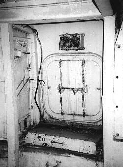
The two side escape hatches were water tight and sealed with rubber gaskets. They were not used very often as the front ramp provided easier entrance and exit when on land and when at sea the cargo hatches on the roof were the only doors that could be used besides the small crew hatches on the roof. Typically, the side hatches were opened only to increase ventilation in the back of the cargo area while on land. In this museum vehicle you can see the large horizontal securing latch that operated the releases on the door, as well as the wire handle on this side that pivoted up to release the holding dogs. To the left are stowage brackets for flashlights, crew canteens and some tools, and vertical roof supports are to either side which frame the hatch opening.
In order for a vehicle this size to float on water it has to displace an equal (or greater) weight of water. Since the LVTP-5 was going to require a certain total amount of equipment and armor weight, the planners kept it afloat by adopting an elongated cube shape to take up a greater weight of displaced water. Although this boxy shape is very inefficient for moving through the water, the shear bulk does replace enough water to the AFV floats when loaded as directed by the designers. The bilge pumps removed any water that entered the hull when the vehicle was floating. That is why you will usually see two different load restrictions in listings for LVTs, the first is for use during ground transportation operations and indicates the total weight the suspension and drive train can handle. The second is usually the water load, or the heaviest load that will still allow the vehicle to float with enough freeboard to keep it from swamping. In the case of the LVTP-5, the need for as much water displacement as possible forced the planners to create the large air spaces and huge bulk of the AFV, it had to be big enough to displace enough water to keep her floating.
When the Marines were ordered to begin mobilizing for action in Vietnam, they had no vehicles in their inventory like the Army's M113 APC. So, in typical US Marine Corps tradition, they made do with what they had, their trusty LVTP-5 Amtracs. By the time the first Marines landed in Vietnam on Red Beach 2, on March 8, 1965, most of their LVTP-5 vehicles had been upgraded to the LVTP-5A1 type. The landing on Red Beach was the first major American military action in Vietnam and many of the 3,500 grunts that came ashore over the next few days arrived on the beach in LVTP-5 Amtracs.
 Picture 3:
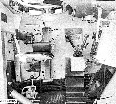
This is the driver's station in the LVTP-5 and this illustration from the Maintenance Manual includes most of his equipment above the forward end of the left track sponson. The driver's seat is the same type we have already seen at the commander's station on the other side of the hull and consists of a support bar bolted at the bottom to the sponson and at the top to the hull wall. A molded seat bottom pan slides up and down the support bar to adjust the elevation of the seat. The two seat control levers are visible in the picture on the other side of the arm pad and they control the seat's position both up/down and front/back. The seat back that attached to the rear of the base pan is also adjustable in height and is removable. Forward of the seat is the box support that has the driver's steering and shifting control lever (called a wobble stick) mounted on top. The transmission is an Allison CD 850-4 cross drive type that functions as a differential, steering unit, transmission, and brakes. Behind the wobble stick, and attached to the hull wall, is the large engine hand throttle (A). On the hull wall behind them you can see a driving instruction plate and above it is the driver's vision cupola with his M17 vision blocks and padded dome hatch. Also on the ceiling is a handgrip (another is on the wall) and a typical US style interior dome light is visible in the vicinity. The box shaped instrument control panel is directly in front of the wobble stick. Down on the floor, to the right side of the seat support, is the actuating lever for the hydraulic motors that controlled the front ramp. Push it forward and the ramp is lowered (after it is unlocked)--pull it back to raise it up.
 Picture 4:
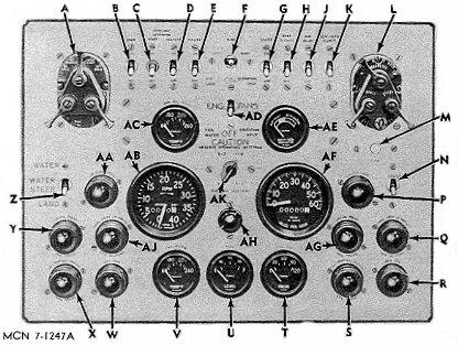
The instrument panel is painted white and the dials are black with white letters. The larger two center dials are the tachometer (left) and speedometer, and the three lower are, from left to right, engine coolant temperature, fuel, and oil pressure indicators. The five red indicator lights at the lower right include final drive oil pressure and engine generator warning lights and those on the left are the auxiliary generator, engine, and engine oil pressure warning lights. The two smaller dials above the tachometer and speedometer are hydraulic oil temperature and voltmeter gages while the large switch group at the upper left controls the vehicle outside driving lights. A similar switch group on the right includes the main engine magneto switch, and the long bank of silver switches along the top edge of the panel control other electrical functions including the turn indicators and the air ventilator blowers as well as the radiator fans.
 Picture 5:
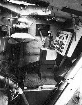
Another image taken of the preserved vehicle we saw previously shows the same general area as Picture 3. In this case, the seat has a black seat pad in the molded pan, but the seat is missing its backrest. Behind the seat on the hull wall is the driver's green radio control box and behind that is barely visible the red emergency hand pull for the engine compartment fire extinguisher system. There is also an external manual pull handle in a recess on the left hull side of the vehicle, to be used if there is no one inside capable of pulling the driver's handle. There are two fixed CO2 tanks in the engine compartment and each time a handle is pulled it completely empties one of the bottles. Since the system has two bottles it is known as a "two shot" fire suppression system.
There were generally three radio control boxes in LVTP-5s, one by the commander on the right hull wall, one by the driver over here, and one mounted on the ceiling between their positions for use of the gunner when a MG turret was mounted. Notice the periscopes are missing from the driver's cupola in this Amtrac, but most of the rest of the equipment is more or less intact. The long handle hanging down beside the control panel is the lock for the front ramp. Before the ramp may be lowered, the lock must be released. The black and white bilge hose is again visible at the lower left, and the handle to control the lowering and raising of the ramp is down on the floor by the seat support. Here, the steering lever is aluminum colored (bare metal), the boot black rubber, the support box is white like the walls, and the floor is flat black with skid plate surface texture, just like the cargo floor.
 Picture 6:
Things can get a little cramped with a driver installed in the seat and you can now get a feeling for the size of the area that we have been examining. Thomas Williams loaned us this photo that was taken in Vietnam in the mid 60's. He says, "This is Vern Bjugstad, in a position he did not get to enjoy very much... the drivers seat. Vern was usually behind the 30 cal." The storage shelf behind his seat is cleared of equipment but the cylindrical air blower can be seen hanging from the ceiling. Typically, up to three radios were mounted on shelves in this area, often including an AN/GRC-5 and/or an AN/GRC-7. These were both identical sets with the exception that the -5 was used to communicate with artillery and the -7 with infantry units. When these radio sets were introduced in the 1950's, different frequency bands were allocated for armor, artillery, and infantry assets and the different radio bands overlapped each other by around 900 kHz, allowing communications between different types of units.
The AN/GRC-7 radio set was typical of the time and composed of a number of radio boxes and associated equipment, all hooked together. The main component was a RT-68 receiver-transmitter using the 38-55 MHz range. These units were FM types and they could be either "continual" tuned by dial, or you could use the presets on the radio face. Also included in the AN/GRC-7 was a RT-70 Receiver-transmitter operating at 47-58MHz range, again with continual tuning or two presets. This was also an FM radio and all these sets were Korean War vintage and very dated by the time they were used in Vietnam. Down at Vern's feet are the brake (left) and accelerator pedals, although they are a bit difficult to see in the shadows. The pedals are more clearly visible in the previous images. Up at the top right of the image is part of the ammo box support for the .30cal in the turret and you can also see some of the manual traverse handle for the turret just to the left of the ammo box support. The black hand crank has been turned up in the stowed position.
 Picture 7:
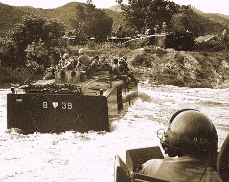
In Vietnam, the LVTP-5A1 played a couple of very important roles for the Marine Corps. Early in the conflict, the Amtrac brought Marines and equipment from assault ships anchored offshore directly onto the beaches. They also acted as assault vehicles and water taxis, transporting men and materials along the coast and inland waterways. Unfortunately, Amtracs were also later used as over-land armored personnel carriers (APC), a job they were not designed for. Although the belly plates were made of armor, they were thin and exploding mines would not only rip off bogie wheels, but rupture the fuel cells under the floor causing catastrophic internal fires. Most Marines preferred to ride outside the vehicle on the roof whenever possible. The Marines in this USMC photo are on a sweep mission near Da Nang Air Base in mid '65. Notice the periscope heads around the edge of the closest driver's cupola and his glass fiber "bone dome" helmet with attached earphones. Crews also wore flak jackets when on missions like this, although when away from direct fire the heavy jacket was quickly dumped. The vehicle up ahead shows the characteristic "dog house" structure on the engine deck that identifies this as an LVTP-5A1 vehicle.
 Picture 8:
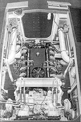
The engines in all the LVTP-5s were Continental LV 1790 liquid cooled gasoline engines with 1,790 cubic inch displacements and 810hp output. They were 90 degree, V-12 units and were mounted in the center rear of the hull with the Allison transmission coupled directly behind. This image is from the LVTP-5 Maintenance Manual again and shows the roof of the LVTP-5 with the large engine hatch removed and the Continental/Allison mounted down inside. Most of the top of the engine is covered with an oil cooler shroud, seen here as the black plate with the small fan on this end. The short pipes on each side would be connected to exhaust headers that would lead up to the exhaust vent in the center of the panel that has been removed for this picture. Large can-type oil bath air cleaners are mounted on each side of the engine compartment and the large white intake ducts bringing them air from the cargo compartment are seen on either side of the top of the picture.
From the air cleaners the air flows through the shorter corrugated aspiration air ducts directly into the carburetor on each side of the engine. Notice the two fresh air flap doors located up on the roof, just forward of the engine opening. These could be opened or closed by the driver to control the amount of outside air entering the air cleaners and then the carburetors--in this picture the right door is open and the left closed. Also next to the left air door is the fuel filler cap with the filler hose extending down to the floor to the fuel tanks below. The Allison cross drive transmission is on this end of the engine and here is shown painted its typical white. The large cylinder crossing above the transmission is the transmission oil cooler, and if you look carefully you will see water coolant hoses running to and from the radiators in their compartments at the sides of the vehicle (not seen here). One coolant hose is seen entering the transmission oil cooler and the other enters the engine down below. The transmission oil enters and leaves the cylindrical cooler via the four smaller hoses on each end. The shifting and speed changing control rod are seen running across the top of the transmission from the left, originating at the driver's position. The final drives can be seen at the bottom of the picture at either side of the compartment.
 Picture 9:
This is a rear end view of the Allison CD-850 transmission. The unit provided two hydraulically selected gear ranges driving through a torque converter. The great advantage of the cross drive transmissions was its simplicity of operation, which greatly eased the task of the driver. By pushing the wobble stick to the left or right he steered the vehicle in that direction when the transmission was in first or second gear. The same action in neutral caused the vehicle to pivot in place with one track going forward and the other in reverse. The Amtrac was braked by built-in disc brakes actuated mechanically by the left foot pedal in front of the driver's seat. This same transmission was the standard in American tanks for a number of years. One of the differences between the LVTP-5 and the 5A1 was the final drive attached to the transmission; the earlier type used a planetary gear system and the later a one-speed spur gear. In this photo the large round access plates at the left and right are for the reverse and low range servos. The speedometer attachment is just above the valve body at the upper right, and the brake band adjusting screws are at the bottom on either side of the case. The control levers for the parking brake are at the top left and right corners of the unit.
 Picture 10:
Other changes that took place in the revised LVTP-5A1 included the removal of the rear rudders and the addition of a box snorkel over the roof ventilators. The new snorkel was the most visible of all these changes (inside the Amtrac things remained pretty much the same) and it included a new air import/exhaust system for the engine. Because seawater could occasionally wash over the roof it could enter the early type exhaust grating in the center of the engine access panel. The raised snorkel structure was designed quickly to solve the problem, the structure sometimes called a "dog house" by crews. Improved air filters were also installed below the new louvers and one is seen here as the silver colored box at the upper middle of this picture, the image taken looking into the Vietnam era engine compartment from the cargo area. The corrugated exhaust ducts you see are leaving the engine manifolds and rising to the new snorkel above. Down on this end of the engine we can also see the two power take-off drives for the radiator fans located in the smaller compartments on each side of the engine. The drive shafts rise obliquely as they exit out of view on either side of the picture, eventually connecting to these side mounted fans in order to blow cooling air through the radiators. The large vertical tube on the far right is the fuel filler pipe that brings fuel from the filling cap on the roof down to the fuel cells below the floor.
 Picture 11:
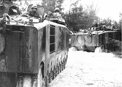
This USMC photo of a couple of Amtracs on patrol shows part of the dog house on the engine deck as well as a Marine in the right side hatch, near the cargo doors. There is no padding on these hatches (as there are no seats below) and the latch is a simple handle to secure the hatch when closed. The long cargo doors have been opened all the way and folded over on the edges of the roof. Notice the Crew Chief in his hatch up front and everybody on the next vehicle riding up on the roof.
There is no doubt about it, the LVTP-5 was not a beautiful AFV by any stretch of the imagination. In fact, if you wanted to create the cheapest, ugliest, most basic boxy shaped armored transport you could, it would probably look pretty much like the LVTP-5. But the Amtrac was not designed to win beauty contests, it was designed as a basic armored assault transport to bring troops ashore and disgorge them and their equipment safely on the beach. In that role the Amtrac performed well, although the early engines required a great deal of attention. Like any AFV pressed into service to provide a function it was not designed to accomplish, the LVTP-5 did not perform well as a battlefield taxi. It was a big target and mines were especially deadly. Once again, the same old lesson was learned the hard way... you can't make an AFV do what it was not designed for. By the mid-1970's, the LVTP-5 was being phased out of service by its new and improved replacement, the LVTP-7.
Two gentlemen/organizations helped provide reference images and information for this series of articles and I am very grateful for their support. As I have mentioned previously, Sgt. Thomas P. Williams, who was with the 4th Platoon, B Company, 1st Amtrac Battalion, and then the 1st Platoon, A Company, 5th Amtrac Battalion in Vietnam, loaned us some interior photos from his collection and also shared recollections from his tour in Nam.
Also, the good people at the Museums Branch, History and Museums Division,
Headquarters US Marine Corps supplied many of the LVTP-5 Maintenance Manual images as well as valuable vehicle operation information.
Return to Page One
