|Home| |CV| |KAFKAF R&D|
|Palmball||Prism-Technique|
|El-Mishkak| |Words-War|
|Book Review| |Article Review|
Rockbolter is the name I gave to the ultrasonic apparatus I designed for my PhD project in the Mining Department , Nottingham University, England, from 1985 to 1988. It was the subject of a patent application No8802105 which was published on 13 September 1989.
A full article about the device and the method used for testing material samples was published in the Journal of the British Institute of Non-Destructive Testing, INSIGHT, Vol. 38 No 10. on 10 October 1996, under the title: A Mode-Conversion Method for Evaluating Elastic Properties of Materials.
ABSTRACT
An ultrasonic apparatus for evaluating elastic moduli of materials was designed. The problem of measuring shear-wave velocity, which could be difficult to overcome with equipment using shear-wave transducers, was solved by a transducer-cell. In this latter, only a compressional wave transducer was used. The specimen is in the form of a prism and the angle arrangement of the specimen and the transducer allowed compressional waves to be refracted either as compressional or shear waves depending on the angle of incidence of the sound beam on the liquid-solid interface. Thus, both velocities could be computed in a relatively simple manner with the help of a special formula, which contains only easily measured variables. The device can be used with existing flaw detectors which are based on transit-time measurement of a pulse-echo. It could also be linked to a computer through a computer interface in order to make a semi-automated system for computing and displaying elastic constants of materials.
The author used no off-the-shelf equipment: in addition to the transducer-cell, which is the subject of this paper, he designed a transducer holder, a power amplifier, a frequency synthesizer, a computer interface, and a computer program in order to control the whole experiment.
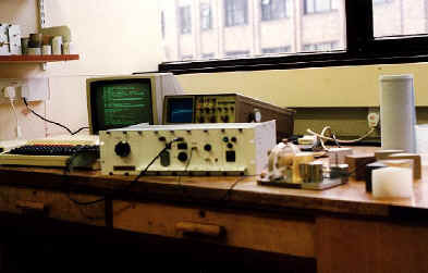
The whole apparatus, from left to right, the BBC computer, the rack system which houses the electronic modules, the transducer-cell and some samples.
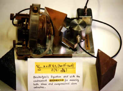
The Transducer-Cell. Notice the special form of the sample under test, and the formula used to compute both shear and compressional wave velocities.
Many British companies were approached in 1988 in order to license the product, namely, CNS Electronics Ltd, Sonatest Plc, and Phoenics Inspection Systems Ltd.
In the year 2001, I created a research lab at Jijel University, Algeria. The main purpose is to carry on doing research in the field of non-destructive testing of materials using ultrasound. I was particularly excited about testing a new version of the transducer-cell that I had mentioned in the recommendations of my PhD thesis in 1988 at Nottingham University.
After acquiring some ultrasonic equipment, I built a new transducer-cell. Theoretical calculations gave a much simpler formula (photo) with quite a surprising result: wave velocities are in this case independent of the rotation angle, which represents a huge improvement over the old version.
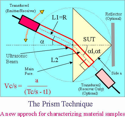
The new version is called the Prism-Technique. Full details of the technique can be found in the following papers:
The initial results indicate that the “Prism Technique” could be used as a reliable testing method for characterizing materials. The main advantages of this method over other more known ultrasonic techniques and especially the rotating plate technique (which shares some of the features) are as follows:
*
There is just one transducer used for measuring the wave velocity of both
compressional and shear waves.
*
Easy and uniform coupling between the transducer and the sample, which
characterizes immersion-testing methods.
*
Formula (1) indicates that the velocities are independent of the incidence
angle, which represents a huge advantage over goniometer methods.
* Measurements are temperature compensated, which means that the velocity remains constant for small variations around the ambient temperature. However, the liquid interface could be used to transfer heat to the sample for taking measurements at high temperatures.
*
The same configuration could be easily adapted to test samples under high
stresses (uni-axial compression, hydrostatic pressure, etc.).
*
A careful selection of the transducer frequency (for this experiment three
frequencies were used, namely, 1 MHz, 2.25 MHz and 5 MHz. But in the end 1MHz
was selected for taking all measurements because it led to bigger echoes, with
almost the same sharpness) bandwidth (improves the rise time of the pulse) and
focal length (to be able to position the near field distance on the main
reflector), would lead to nice and clean echoes, no signal processing is
required, and thus time-of-flights are measured using just the cursors of a
digital oscilloscope.
* Despite using just a line marker that indicates the exact placement of the sample in the transducer-cell, measurements are repeatable, with minimum errors. This could be improved further by the use of a clamp, in order to position with precision the specimen in its place.
E-mail: bouhadjera@mail.univ-jijel.dz