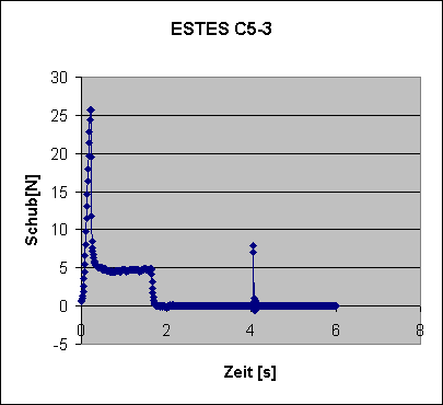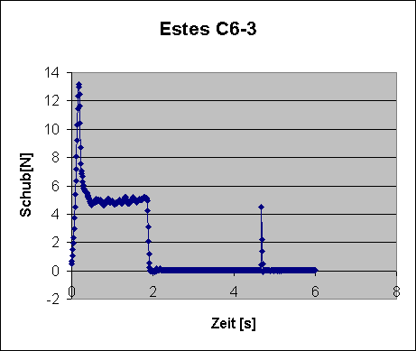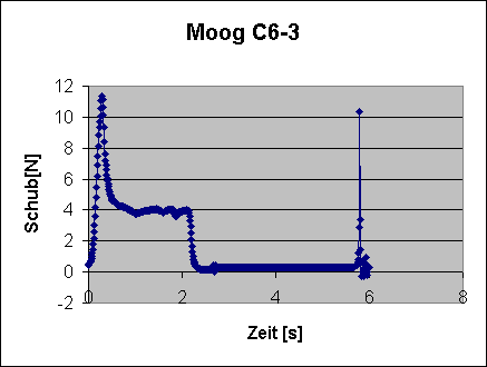
There are two manufacturers selling their products here in Germany: Estes and Moog. Estes didn't certify their whole range of motors here, but still has the wider variety than Moog who only make A8-3, B4-4 and C6-3 motors.
Here some measurements in table form:
| Motor | Impulse | Ejection | Delay | Contents |
|---|---|---|---|---|
| ESTES C6-3 | 9.96Ns | 0.09Ns | 2.7s | 14.4g |
| ESTES C5-3 | 9.88Ns | 0.16Ns | 2.3s | 14.6g |
| MOOG C6-3 | 9.77Ns | 0.27Ns | 3.5s | 16.0g |
Here are the thrust/time charts:


Happily all three motors are close to the 10Ns limit. But the delays vary wildly: the ESTES motors are short and the Moog too long. The C5-3 differs in its whole characteristics from the data published by Estes. The delay is only about 2.3s and instead of 2.1s it's burning time is only 1.7s. The Moog C6-3 has the longest burning time but delivers the weakest thrust.
This is data from a very limited sample (1 each) and it isn't said that all motors behave like this one. We'd need a bigger amount of motors to do some more testing - any manufacturers or dealers who want to sponsor?
Here's annother thrust/time curve of a genuine german
motor called the HELD1000.

It is basically a C2-0 and was designed for rocket gliders. Its OD
is about 15mm.
If you want to have a look at Juergens test stand: 
The test stand is made of a frame of rectangular aluminium profiles. The rocket motor is mounted on a lever which has bearing and sensor at different ends. The sensor itself covers a range of 0-10N. The effective range of the test stand can be changed by mounting the motors at different locations on the lever (basic physics).
...and this is the force sensor he's using: 
Juergen uses this sensor because he got it for free: it was salvaged
from a semiconductor testing device.
If you want to build your own test stand, look for not too expensive
electronic letter scales. Some of them have a range of 0-20N with a resolution
of 0.01N. Peek the sensor and some of the electronics out of them and feed
the signal to some ADC connected to your PC/laptop.
Start sampling as soon as the sensor delivers values above a certain
trigger level and store the data together with some RTC clock data to a
file in form of time/force pairs. You can later reformat/filter/manipulate
that data and plot nice charts using your favourite spreadsheet program.
Here are some pictures of motors in action:


On the left picture you see a Moog C6-3 under test. Some Motors are allowed to eject from an aluminium pod (blue) to measure the power of the ejection charge (hence the numbers in the table above showing the additional impulse a model would gain from ejecting the motor).
The right picture shows a 24mm motor with an aluminium case which is used in professional fireworks.
And: No! No one is standing that close to a motor under test to take pictures! This photos have been taken by a remote controlled camera.
back to my homepage