Cole's Large Hit & Miss
February 2003
For Christmas, 2001, Hazle gave me the Cole's Power Models Large Hit and Miss
engine castings. I had recently completed my first internal combustion engine,
Dick Upshur's Farm Engine as described in Strictly IC magazine and
was ready for a new challenge. I had worked from castings previously in both the
Ericsson Pumping Engine and the Essex Fan, but being all cast iron, this engine
presented a bit more challenge. Another interesting bit of metalworking was the
multitude of parts that in their complexity precluded machining the parts in
their entirety. I will point out some of them in the photos that follow. And as
a warning to others that go down this road, I will say that if you are not a
good filer (as with a mill file), you will be after you complete this little
jewel! And now to the photos: (as usual, most of the small photos link to
larger versions)
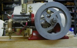
 Here it is in running condition
(sorry, no larger view here, detailed photos will follow). I haven't yet made a
proper stand to contain the ignition system, so things are a bit chaotic. Right
now everything is stationed atop my table saw, and the engine stabilized with a
screw clamp which is out of sight to the right of the photo. The engine is
fueled with propane - the tank is in the background, and a temporary convection
cooling tower keeps the cylinder temperature under control. The brass ball in
the near side flywheel is the governor weight. You can see the adjusting screw
in the top of the flywheel.
Here it is in running condition
(sorry, no larger view here, detailed photos will follow). I haven't yet made a
proper stand to contain the ignition system, so things are a bit chaotic. Right
now everything is stationed atop my table saw, and the engine stabilized with a
screw clamp which is out of sight to the right of the photo. The engine is
fueled with propane - the tank is in the background, and a temporary convection
cooling tower keeps the cylinder temperature under control. The brass ball in
the near side flywheel is the governor weight. You can see the adjusting screw
in the top of the flywheel.
A feature of this engine is an ignition cut out, shown in the photo below
(click for enlarged view). The tab in the lower right of the photo raises the
curved lever, opening the points. 
When the governor is engaged, letting the engine "miss", the
exhaust valve push rod remains in the forward position, keeping the points open.
So, you only get a spark when a power stroke is required. The whole governor
system is pretty complex, and it took a bit of thinking to see how everything
was related!
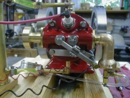
 In
this photo (at least in the enlarged view) you can see parts of the governor
mechanism. The brass ball is the governor weight and through the flywheel is the
arm that controls the pushrod latch. Below is a drawing of the governor and
associated parts, which will help explain its operation.
In
this photo (at least in the enlarged view) you can see parts of the governor
mechanism. The brass ball is the governor weight and through the flywheel is the
arm that controls the pushrod latch. Below is a drawing of the governor and
associated parts, which will help explain its operation.

When the engine speeds up, the governor weight (36) is thrown outward by
centrifugal force. As the flywheel rotates, the latch (34) is pressed down and
as the cam moves the pushrod forward, it is latched by the two wedge shaped
blocks seen just above the cam. As the engine slows, the governor spring
restores the disk to its original position and when the cam moves the pushrod
slightly forward (left in the drawing) the latch releases, allowing the exhaust
valve to function normally again. As noted above, while the exhaust valve is
latched open, the points are held open by the operating plate (29) acting on the
points lever (41).
 And
now, a few more details of the engine:
And
now, a few more details of the engine:
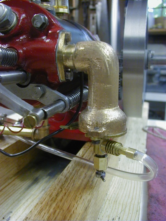
The carburetor is a bronze casting, which presented some interesting
exercises in holding irregular shaped work! The needle valve assembly, seen
below the carb body is adjustable vertically to place it properly in the
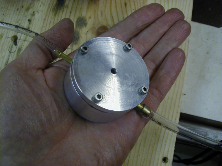
venturi. I am running the engine on propane and the regulator is on the other
side of the engine. The regulator (shown below) is a demand regulator. That is,
it only delivers propane when a vacuum is present on the downstream side. My
thanks go to Jerry Howell, Richard Williams and Tom Stuart for generous advice
in building the regulator. The engine has about 6 to 8 hours running time now, and is still on its first bottle of propane.
Here is a photo of the front end.
And the engine in action:

I had the very devil of a time getting this engine to run, and my friend Marlen Baerenwald came to my rescue. At his advice, I had rigged up an electric motor to turn the engine while I twiddled the carburetor adjustments. It turned out that I needed to turn it a whole lot faster than the 3-400 rpm I was using. Marlen came over, put on a bigger
pulley and at around 800 rpm, she took off running. So thanks to Marlen, too!.
What would we do without friends?
And last, but certainly not least is the piston rod. I spoiled the bronze
piston rod that Cole's provided, and Gary Heidt made this one for me. He is a
student (like me) at DeKalb Tech, and was studying the solids feature of
Mastercam. He drew the piston rod from a 3-D drawing I had made, gave it
considerable refinement, then machined it on the new Fryer CNC Mill at DeK Tech.
Some of the profiling was done with 1/16" ball end mills, and he managed to
break only one in the whole process! Thanks, Gary!!!! (be sure to check the
large view)