The Gearless Hit and Miss Engine
New 12/06/2004
This engine was originally shown in the Home Shop Machinist, August, 1994 and months following. The design is by the late Philip Duclos, any of whose engines are worth replicating. It was a fun project, taking me just about 4 months of off and on shop time to complete. I made a few modifications to Phil's design, some of which led to a bit of grief in getting the engine to run well, but after a bit of trouble shooting and help and advice from Dale Detrich the engine now starts on the first or second pull of the starter cord and runs beautifully. Following are some photos taken during the construction with notes on techniques and assorted problems and solutions. As always, I welcome your questions or comments on this and my other engines.
Click on the photos for a larger photo.
|
|
|
| The starting place is usually the base, so here we see the first assembly of the base components. All this steel makes for a solid foundation for an engine. | More parts now have been made and a trial assembly started. The cylindrical piece to the right side of the base is the tool that is used to check the centering of the crankshaft below the piston. The OD is a close fit in the cylinder and the peg on the near end is just smaller than the distance between the crank throws. |
|
|
|
| The cylinder jacket is a fairly complex part on this engine. Here we have done the initial OD turning from a square solid and are boring for the cylinder liner. | Milling operations have been finished and we are preparing to start cutting the cylinder fins. The cylinder jacket is mounted on a mandrel for this operation. |
|
|
|
| I have found (by my usual trial and error methods: lots of trials and lots of errors!) that to successfully cut deep slots with a parting tool, it must be exactly perpendicular to the part. Here we set the parting tool with an indicator. Note that I have ground a parting blade from a standard 1/2" square lathe tool. |
Cylinder fins are progressing nicely here. |
|
|
|
| The final operation is to round the edges of the fins with a profile tool, making for a well detailed part, one of the hallmarks of Duclos' work. | Making the head is next. Here we have turned the haed, recessed the under side and drilled for the head bolts and spark plug. The top fins are being milled with a slitting saw. |
|
|
|
| To slot the valve covers accurately, they have to be indicated for parallelism. | Then they can be slotted with the 1/16" slitting saw. |
|
|
|
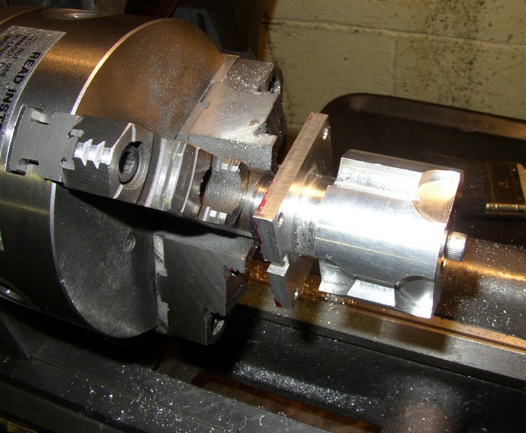
| Here we have finished all the parts of the head, complete with needle valve, valves, valve housings and covers. I used Bob Shores' method of C clips to retain the valve springs. | As is my custom, I made a split collet to snug the flywheel to the crankshaft. Here the blank has been bored and now reamed. |
|
|
|
| The cross slide is set over to the correct angle and the outside of the collet turned. | Before removing the collet, the fit is verified, then the collet is parted off. It will be drilled while in the flywheel, using coordinate drilling (aren't DRO's wonderful?). |
|
|
|
| Finally the collet is split with a jeweler's saw. The slot
need not be wide due to the close fit of the collet and the
crankshaft.
|
Here it is, all done! |
|
|
|
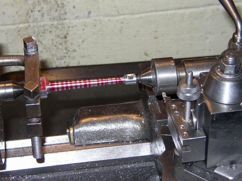
| Laziness has set in! I didn't want to take the trouble to set the tailstock over to taper the piston rod, so I drew it in Autosketch and measured the diameter every .1". I then turned to the various diameters and finished the taper with a file. | This rather primitive approach yielded a pretty good taper, I think. |
|
|
|
|
With all assembled, it is time for a run in session. |
Here's a little closer view of the left side. |
|
|
And we are all done except for the painting! |
|
And now the right. |
After the run in was completed, I had a hard time starting the engine. The original piston was aluminum, and was made slightly undersize to compensate for expansion, so compression was too low to suit me. I made a cast iron piston and got much better compression, but still had starting problems. In April, I took the Gearless to NAMES where I camped out next to Dale and Jan Detrich. Dale has a Gearless that he made some years ago and it runs beautifully. We compared and tested off and on most of NAMES, and Dale was almost as mystified as I was, but he opined that it might be a valve problem at speed, since the valves seemed to be holding compression well when cranking. When I got home, I removed the valve cases and examined them under magnification.
Now here is where another of my modifications had gone awry. Phil had made the valve cases all one piece. I thought that making the body out of aluminum and inserting a steel valve cage would be simpler than trying to machine the valve seat down inside a hole as he described. The problem was that I had not pressed the valve cages in sufficiently. There was about .030 of the aluminum body above the cage and the valves would stick slightly open when the engine sped up. I chucked a half inch end mill in a hand drill and cleaned up this shoulder, and SUCCESS! Now the baby starts easy and runs beautifully. Thanks, Dale!