Theory
Spread spectrum (SS) is a technique in which the transmitted signal, which occupies a relatively narrow bandwidth, is spread over a very wide frequency band. Although this is not efficient from the point of view of bandwidth utilization, yet, the fact that the power spectral density of the SS signal is very low enables it to coexist with narrowband signals that already occupy the same frequency. SS signals just add a slight increase in the noise floor that the narrowband receivers see and hence, can be considered transparent to unintended receivers. As for the SS receiver, it does not see the narrowband signals since it is listening to a much wider bandwidth at a specific code.
For example, an ordinary AM signal utilizes a bandwidth of 10 kHz. Consider that the spread spectrum signal is operating at the same carrier frequency as the AM signal and has the same power Ps as the AM signal but a bandwidth of 1 MHz. Then, in the 10 kHz bandwidth of the AM signal, the power of the SS signal is
Ps x (104/106) = Ps /100
Since the AM signal has a power Ps, the interfering SS signal provides noise that is 20 dB below the AM signal. This is illustrated in the figure below.
fig.1 A narrowband signal and a direct sequence spread spectrum signal on the same carrier frequency.
There are five types of SS techniques, namely:
1. Direct Sequence (DS) Systems.
2. Frequency Hopping Systems.
3. Time Hopping Systems.
4. Pulsed FM Systems.
5. Hybrid Systems.
Direct Sequence is perhaps the most widely known SS system and it is relatively simple to implement. The following section discusses in more detail DS systems, as they are the most commonly used systems in implementing CDMA technology.
i. Direct Sequence Spread Spectrum (DS-SS)
In a DS-SS system, the transmitted digital signal (which is already modulated by a certain carrier) is amplitude modulated by a very high rate binary stream of digits. Thus, if the digital signal is d(t), the modulated signal is
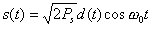
then the DS-SS signal will be
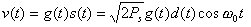
where g(t) is a Pseudo-random Noise (PN) binary sequence having values ±1, Ps is the signal power.
fig.2 A DS-SS transmitter.
The sequence g(t) is generated in a deterministic manner and is repetitive. However, the sequence length before repetition is extremely long that we can assume that the sequence is truly random, i.e., there is no correlation at all between the value of a particular bit and the value of any other bits. Furthermore, the bit rate fc of g(t) is usually so much greater than the bit rate fb of d(t) that we say that g(t) "chops the bits of data into chips", and we call the rate of g(t) the chip rate fc, retaining the words, bit rate, to represent fb. The chip rate fc is a multiple of the bit fb, hence each transition in d(t) coincides with a transition in g(t).
To see that multiplying the sequence s(t) by g(t) spreads the spectrum, we refer to fig.3 which shows a data sequence d(t), a PN sequence g(t) and the product sequence g(t)d(t). The product sequence is seen to be similar to g(t), indeed if g(t) were truly random, the product sequence would be another random sequence g'(t)=g(t)d(t) having the same chip rate fc as g(t). Since the bandwidth of the signal s(t) is nominally 2fb, the bandwidth of the DS-SS signal v(t) is 2fc and the spectrum has been spread by the ratio fc/fb. Since the power transmitted by s(t) and v(t) is the same, i.e., Ps, the power spectral density Gs(f) is reduced by a factor fb/fc.
fig.3 The waveforms of the data stream d(t), the chipping waveform g(t) and their product.
To recover the DS-SS signal, the receiver shown in fig.4 first multiplies the incoming signal with the waveform g(t) and then by the carrier. The resulting waveform is then integrated for the bit duration and the output of the integrator is sampled, yielding the data d(kTb).
fig.4 A DS-SS transmitter.
fig.5 A complete DS-SS communication system.