Engine
Gearbox
In the Chassis
Engine
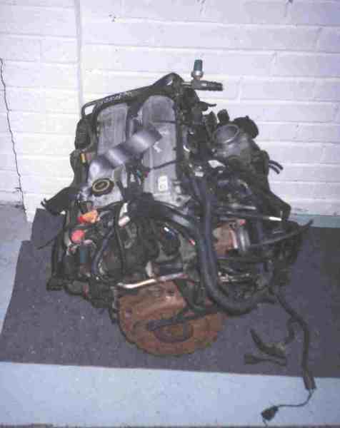
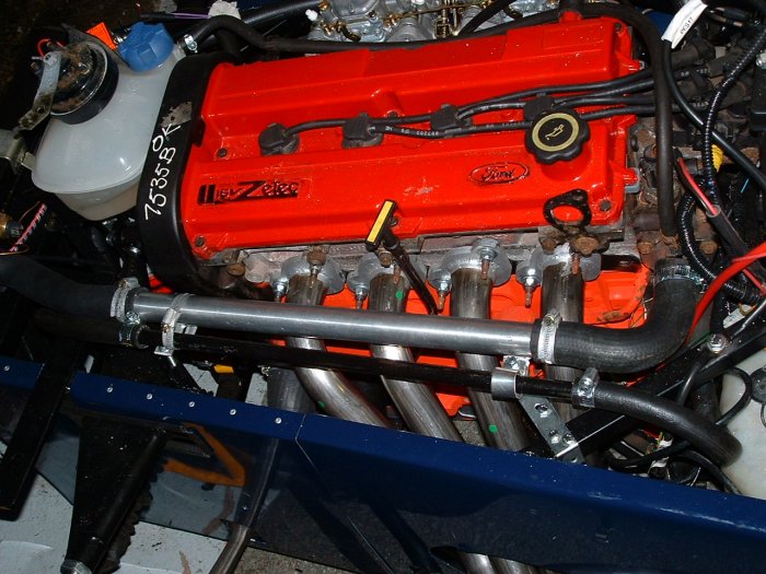
Preparation: The engine came with its Mondeo injection system and manifold, it was covered in sensors, wrapped up in various vacuum pipes etc. Most of this is to do with emissions control. It looked like a rats nest as can be seen from the photo:
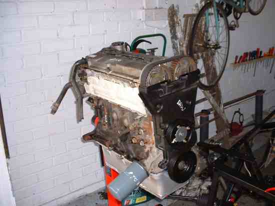
I striped this rubbish off along with the various brackets. Removed the exhaust and inlet manifolds and removed the clutch and flywheel. Next I purchased an engine stand from Screwfix (£30+VAT and worth every penny) and my mate Anthony came round to help lift the engine onto it. The result:
Overhaul: The next question is how far to go with the overhaul. The breakers were vague about the mileage of the engine but suggested around the 60K mark. The engine didn't show any outside signs of wear, tear or leaks so I was quietly confident. My plan was first to check out the bearings and then replace if necessary. So I dropped the sump off and started to investigate.
Main Crank Bearings: I took the caps off and checked the state of the surfaces. All looked in excellent condition apart from the centre thrust bearing which had a slight mark on it. I took some advice from my dad who said it looked fine so I replaced the caps, torque set them and left them alone.
Big Ends: Some background work uncovered that the big ends were the weak link of the Zetec engine and replacement of the big end bolts was advised. I took the caps off the ends and inspected the bearing surfaces…all was well, so replaced the caps and replaced the bolts with new ones from Ford. I considered replacing them with uprated ARP bolts (or similar) but thought I'd leave that for a winter upgrade at some time.
Cams: I took the cam cover off and checked the condition of the cams. No sign of any unusual wear so I checked a couple of bearing surfaces, which were fine. The pre-1998 Zetec (I think the year's is right) uses hydraulic cam followers that have a reputation of sticking if the engine has been poorly maintained so I carefully inspected the follower action to see if anything was sticking down. Nothing was, but it doesn't prove it won't when the engine is up and running but it’s a good sign.
Sump, flywheel and clutch: The sump on a Mondeo is pretty deep and if not modified would drag on the ground when installed in a se7en type sports car. The modification needed is to lop the bottom off it. This causes problems as it reduces the capacity and oil is free to surge from one end to the other potentially causing the oil pickup to be above the oil level… no oil to the engine is not healthy. This is solved by building the sump outwards at the back and fitting baffle plates within the sump. On the Pinto engine this is pretty straight forward as it is a steel sump and Joe Bloggs welders can do the honours. The Zetec sump is aluminium which needs a dam good welder to do it right.
Tiger do offer a modified Zetec sump (£130+VAT I think) but I had heard stories of the Tiger sumps that didn't fill me with confidence so I looked else where. Westfield do a sump for about £100 more than Tiger, Raceline do a brand new cast sump for a lot more, but I went for the Dunnell sump at about the same price as the Westfield one. I sent my old sump away and I got back a very nicely engineered sump with plenty of baffling and a modified pickup pipe. The picture below shows the sump, the pickup sits between the baffles.
Fitting a Zetec engine to a Type 9 gearbox requires some modification of the flywheel. Again, I went for the Dunnell flywheel and clutch. Dunnell lighten the flywheel, fit new ring gear and modify it to take the CVH clutch. A spigot bearing is also needed to fit the Type 9 box to Zetec. This was knocked into the hole in the end of the crankshaft.
Refitting the flywheel was a quick job, now lighter than when it came off. It was a good job as once bolted on I realised I hadn't fitted the adapter plate (as Hommer would say: "DOH!"), I realised quickly so the thread sealer hadn't set. Fitting the clutch to the flywheel was a simple job as I borrowed an alignment tool. Obviously with something spinning at 6000rpm and this heavy you don't want it off centre.
Alternator: The Tiger kit is supplied with a Lucas 101 alternator, Vee pulley, mounting bracket and drive belt. But, I suppose to keep the cost down, the pulley hasn't got a key slot in it and the alternator has. So an hour with the needle file was spent!
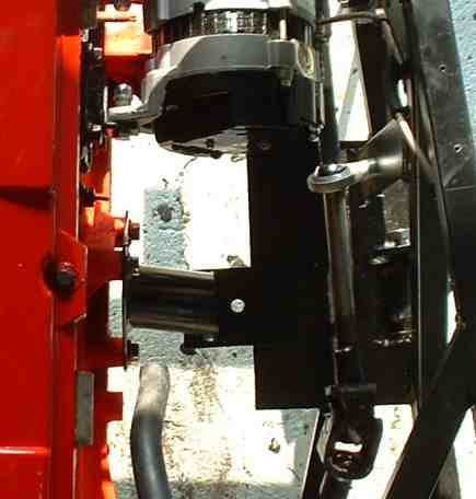
The supplied mounting bracket was poor. The pilot holes pre-drilled to line up with the block mounting points were badly measured so the mounting holes had to be re-worked. The gap between the two angles of the bracket which the alternator body should fit into was slightly too narrow (too wide and you can pack out…easy to fix) so again, re-work carried out. The next problem was that the mounting holes for the alternator pivot were not far enough out so the body of the alternator hit the back of the bracket before a bolt could be but through the pivot…more re-working. The whole design of the bracket is poor, it places the pivot point equally between the 2 other pulleys so when you swing the alternator up and down very little difference is made to the belt tension… the bracket will be high on the replacement list.
Water Pump: The original Mondeo had other ancillaries driven off the drive belt whereas the Zetec installed in a Se7en just has the belt driving the water pump and the alternator. The original belt path meant that the pump spun anti-clockwise whereas now it needs to go clockwise. The pump from the Escort / Zetec set-up rotates clockwise, I bought mine from Dunnell. This unit has bigger vanes in the propeller than the standard ford item. I'd rather be struggling with an engine that’s too cool than one which is too hot.
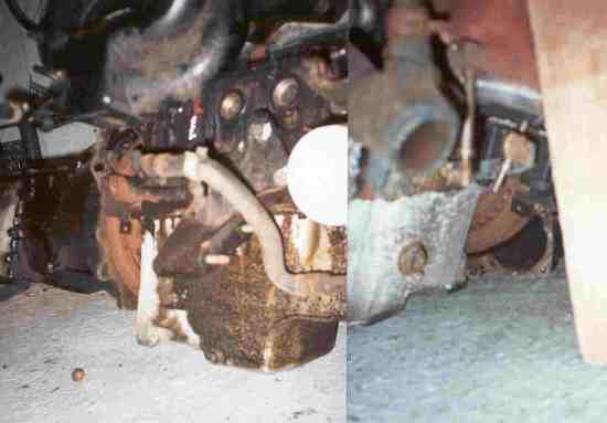
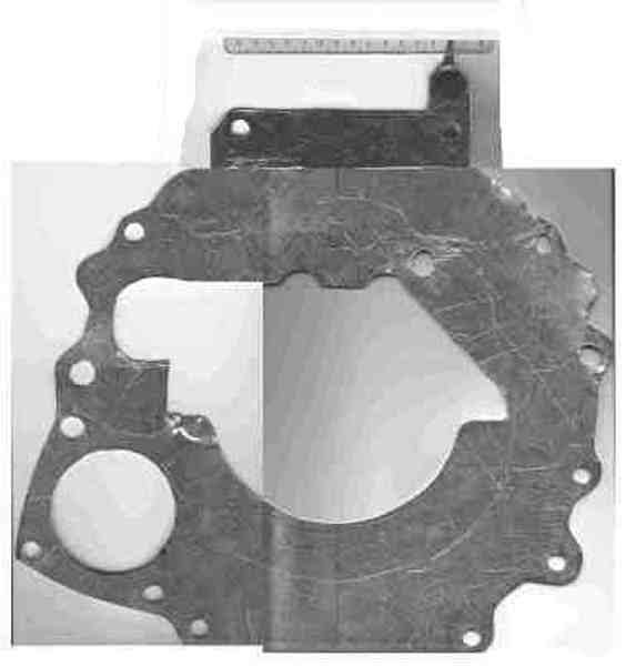
Adapter plate: The Zetec engine is a lot skinnier than the Pinto engine that normally attaches to Type-9 gearbox. This means a plate needs to be made to cover the gaps up…unless you want crap getting in your clutch. The following picture shows the gaps with the flywheel visible either side of the engine when I trial fitted the box against the engine.
Gearbox
Preparation: The gear box came in for some heavy wire brushing and a coat of paint. The large metal mounting bracket was removed from the smaller section of the mounting bracket by drilling out the big rivets and hitting it with the big hammer. Other than that not much else was done.
Overhaul: The type-9 box has a reputation of being pretty reliable and hard wearing. I checked it went in to every gear and turned OK and left it at that. If it gives problems once in the car running it isn't a massive job to drop the box out and get an exchange box. The price of which makes doing it yourself hardly worth it. The only item to be replaced was the clutch release bearing, a few quid from the local factors. Slightly fiddlely job to do as to release the old bearing you have to release the fingers holding it in hidden behind the clutch fork. The only thing left to do was to refill it with oil. I tipped it up and drained what I could (there is no drain plug), then refilled it.
Remote linkage: Unless your name is Clyde and have arms 7 or 8 inches longer than normal, a remote gear linkage is required to put the gear stick in a comfortable position rather than tucked up under the dash.
I read about the poor gear selection of various Tigers and people moaning about the Tiger remote gear linkage, then I saw a picture of the device… it consists of a strap between the remote lever and a cut down lever in the top of the box. Where as the Westfield remote takes a shaft out of the back of the tail of the gearbox and relocates the original gearstick a few inches further back, as can be seen in the following pictures:
The Westfield remote extends the action of the selector shaft backwards, both the fore/aft and rotational motion of the shaft is transmitted efficiently, where as with the Tiger system the fore/aft motion is OK but the rotational motion is compromised as the straps will flex and the play at each pivot will make things worse. Add to this the fact that the Tiger remote is bolted to the chassis with the gearbox moving on it bushes and it's no wonder the system doesn't work too well. The Westfield remote isn't cheap but it’s a well designed, well engineered bit of kit that does the job. Here is a picture of the "remote" in place, the photo doesn't show much.
The only short coming of the Westie design is that the shaft needs to come out of the tail of the box. I removed the cover plate out of the tail and cut a hole in it for the shaft so to minimise the hole left for dirt to get in. Some people leave it open on Westfields, I might make a gaiter for it at a later date.
In the Chassis
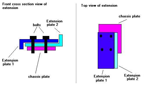
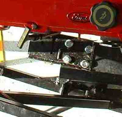
Engine Mounts: The Tiger CAT chassis was designed to take the Pinto engine, not the Zetec. This becomes evident when you look at where the engine mounts are on the block. The Pinto has mounting points at the mid point each side, the Zetec has the passenger side mount well forward. This means the mounting plate on the chassis needs extending forward by 3 or 4 inches. I did this by finding some lengths of steel cutting them down and bolting them to the existing chassis plate to make my extension. I used 2 angled pieces of metal sandwiched together to form a very rigid extension.
How do you fit the engine and gearbox? Well I went for the chassis up and slip it under technique. This was done by jacking the front end of the chassis up, tail on the floor then rolling the engine and box in and under on a trolley, then dropping the chassis down over them…that was the plan anyway.
Coupling: First Job was to couple the engine and box together. This didn't take long, just gently eased the 2 up to one another and dropped the bolts in. This was done on the trolley.
Chassis lift
: We dropped the chassis rear onto the floor then clamped a lump of wood across the chassis about where the gearbox mounts are. Then proceeded to jack the front end up, moving the stand backwards down the chassis towards out wooden cross member. Once the stands where under this wooden cross member we kept jacking and raised the stands until the nose of the chassis was pointing to the roof…. Just enough head room to slide the engine in!You are thinking "why didn't I hire a hoist like everyone else?", well I'm a tight Yorkshireman and I saw what the hire shop wanted for a weekend hire, so it was the this adhoc attempt first!
Slide in: First snag, the castors I'd used to build my trolley where supposed to take 45kg each. I figured the engine was about 80kg and the gearbox about 40kg, so a castor on each corner should cope. The problem was they could cope with the smooth concrete inside the garage, but when lining up the trolley just outside on the rough concrete the wheels at the engine end broke up a bit. I now had a 120kg sledge rather than a trolley!
Once onto the smoother concrete inside the garage the trolley/sledge wasn't too bad to move and my dad and I manovered it under the chassis (I helped as well). A little bit of extra jacking and tipping the gearbox tail down coaxed it in.
Chassis drop: We now performed the reverse of the chassis lift, moving the stands forward until the nose was on the ground. At this point I fitted the engine mounts to the engine. Because the engine was now higher than it would be the mounts were higher than the chassis mounting plates so as the chassis was then lifted the engine was lifted up too. The same was done at the gearbox end, and so the trolley could be removed. The chassis was then jacked up and put on its stands ready for the engine position fine tuning.
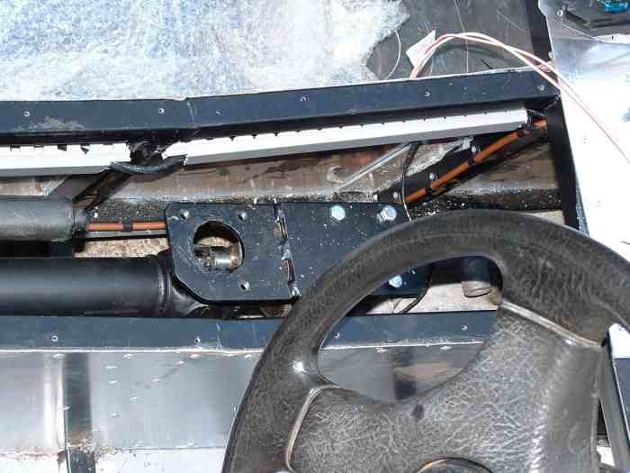
Once in vaguely the right position, the next problem became apparent. As well as the passenger side mount needing extending, the drivers side mount needed extending inward. The picture shows the problem.
- Engine mount - Driver's side
- Engine mount - Passengers side (with extension fitted)
As with the other engine mount, a couple of pieces of angled steel bolted to the existing chassis plate extended the mount.
Engine Position: As the mounting problems show, the Zetec is not a direct replacement for the Pinto engine. This is again evident when positioning the engine. As the induction and exhaust are the opposite way round on the Zetec engine, this means that the carburettors have little clearance with the brake master cylinder and brake lines. The engine must be off set to the passenger side to avoid them along with careful routing of the brake pipes. Offsetting the engine can also been seen as a way of counter balancing the driver…. Well its one excuse!
After figuring of the optimum offset the next problem to figure out is what height to set the engine at. The extra mounting plates gave some lift but I found that the clearance of the trumpets over the side chassis rail was a bit tight to get the air filter in. I fitted a spacer either side on the engine mounting bush to give it a bit of extra margin.
Filter: I liked the look of the big foam sausage filters sticking out of the side of the bonnet so plumped for one of those. I went for the Pipercross PX600 with the biggest clearance…. The more space the engine has to breath the better. Because the clearance with the chassis side rail was tight I had to go with a blank back plane and cut the holes for the trumpet myself offset from the centre so as to fit in the chassis.
Cooling system: Another triumph for the Tiger kit - the set of hoses supplied don't come close to fitting the Zetec installation in a CAT. In fact the bottom hose of the water pump points the wrong way, back towards the bulkhead. I salvaged what I could, things weren't that bad, I found I could use a lot of the angles in the hose selection and only had to buy one large hose from Halfords. I ignored the manual and sited the expansion tank in front of the timing belt cover in the nose. This left plenty of space at the bulkhead end and kept the hose runs short. Here is a diagram of my set-up:
I decided to put the Tiger one the road with an aero screen so SVA wound be simpler. This meant I didn't need a heater so the heater was shorted out of the cooling system.
I didn't like the fan arrangement on the Tiger loom so I fitted a Kenlowe fan and thermostatic control, for accurate and ample cooling operation. I also wired the fan via a relay so that it did not run on once the ignition was switched off.
The system was filled with water to figure out the volume, then drained to flush the crap out of the system, and then refilled with anti-freeze/water mix to the appropriate amount...60/40 if memory serves.
First Roar: Starting the beast for the first time took some doing. First turn of the key and the engine turned over, which was a good start. The bad thing was it didn't run. After a number of attempts the engine sounded like it was about to run, but it just wouldn't catch. So it was back to basics. I could hear the pump running so I assumed that the fuel was getting through...I could smell petrol at the carbs and it had been sounding like it was half firing. I checked the that the ECU was driving the coil pack by putting an LED across the 12V and ground pins of the coil plug. As the engine spun over you could see the LED flickering as the ECU switches. I checked the resistance of all the plug leads and fitted the new spark plugs. Still it wasn't firing up. At this point I was getting a little concerned... had I done something stupid? I had visions of the flywheel not being on correct so the VRS pickup was wrong...but the flywheel only went on one way, a check in the Haynes manual proved this. Next I decided that I need to prove that the fuel was definitely getting through, even though I could here the pump buzzing away. I disconnected the fuel pipe to the carbs, turned the engine on, the pump ran...no petrol! A re-check of the pump proved that the pump was wired up wrong. Once the connections were swapped the fuel came through. Next starting attempt was a winner....sounded great, I was grinning like an idiot for days!
At this point I didn't have a temperature gauge set up so I didn't leave it running for long. But once the dash was working and I could tell how hot things were getting I started the motor and let it get up to temperature. It all worked fine. Fan cut in, engine temperature settled at about 90degrees, top radiator hose needed a little tightening to stop a small leak and that was that... the engine that had been in the garage since last October was a runner.
Silencer: Up to now I had run the engine with the silencer just pushed on the end of the pipe. Now I had the rear body work on it was time to fit the mounting bracket. I did this by bending one of the metal straps that Tiger gave me for extra support for the rear body (couldn't figure out where this strap could possibly be of use) into an L shape. I bolted the 2 rubber bushes on the end of the bracket and to the exhaust mounting tab then taping 2 holes into the chassis rails underneath the car, on the outside rail and one on the first rail under the seat. Ruth's comment was that she will definitely burn her leg on this before too long on exiting the Tiger
(Not because I'm a klutz....honest).