Rack
: The rack is simple to fit once you have the correct bushes. Why don't Tiger supply these in the kit? The rack is a type IV or V Cortina model, which Ford gave up supporting long ago. The only place I found to have bushes was Superflex. Since fitting the rack I have read on a couple of websites that it is worth considering fitting a quick rack at day 1… oh well it's fitted now.If I were doing the job again I would have fitted the lower steering column to the rack BEFORE fitting the rack to the chassis…. I found out it’s a lot easier.
The manual says to cut 4 or 5 threads off the ends of the rack. Having read a few other reports, problems in getting the tracking right follow if you don't.
Column: As I mentioned above, fit the lower steering column to the rack before fitting the rack. The rose joint of the lower column bolts to chassis side member.
The upper column was a pain. The column I got had been damaged by someone screwdriving the lock so I had a replacement barrel to fit. Getting the old one out was no easy matter. There is a circlip holding the thing in the outer housing. Normally you could release this through a slot in the housing, but when this column had been vandalised the whole barrel and circlip had been rotated making it a fight to get it out. It wasn't made any easier by the fact the replacement barrel was of a slightly different design (which I found out once it was removed). The housing suffered a bit of damage but as it will be out of sight I wasn't too worried.
Hubs: The front hubs turned out to be in good shape. No play and free running so a good wire brushing and a coat of paint and they were ready to be fitted.
Arms & Legs: The shortened legs (legs…… I thought it was going to have wheels) supplied by Tiger proved troublesome. The welding was a bit crap so when fitting them into the hub uprights I could not drop them down to the require height of 90-95mm. The welds were proud stopping me getting the last 5mm - so out with the file. As described in the manual the legs need to be set at 90-95mm, this is my interpretation of what is meant:
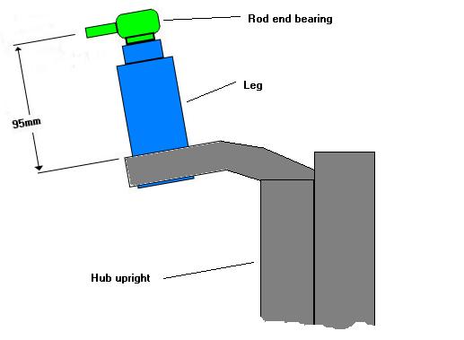
The track control arms that I used were brand new. I went for branded pattern items (not Ford…too expensive) so should be reasonable quality. The top pivot arms need bushes pressing into either end, I asked my friendly garage to fit these for me with their press when I took my Golf in for it's service… I don't think they bothered to charge me for the little job, they also fitted the springs to the coil-over-shocks for me whilst they were at it. The bushes that go into the trailing arms went in easy enough with a mallet
(if at first you don't succeed - bash it). The body work needs to be fitted before final assembly of the front suspension so I just trialled it at first. It seemed to fit OK. The picture below shows the front right suspension set up.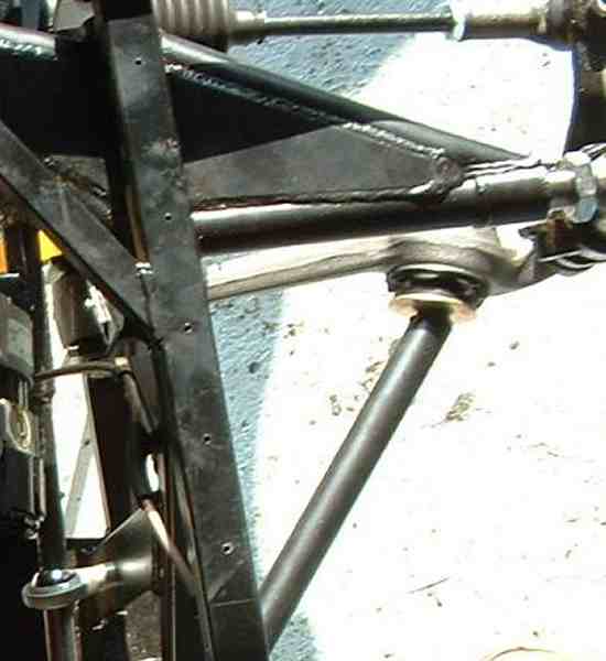
Assembly: As the suspension components poke through cut outs in the body work and I was sending the body panels away for painting, I couldn't fit the suspension until late on in the build after the panels were painted and fitted. This caused a few awkward bits… fitting the TCA and trailing arm once the engine and ancillaries were in place was a pig of a job. But after an hour or so wrestling with the spanners under and over the chassis I got them in place.
Angles: Setting the correct camber and toe in angles is not that easy, especially when the chassis is still on stands. To set things up properly the suspension should be at it natural idle position, not at the end of the travel as it is when the chassis is on stands. To get round this to get an initial setting (as suggested in the manual) I substituted the shocks/springs for a pieces of wood. The wood was drilled with holes 260mm apart to give a suspension position about half way through its travel.
Camber: First I positioned the steering to put the left hand wheel in the straight ahead position and put a spirit level across the rim to check the camber angle. The manual suggests 0 degrees. To alter the angle I undid the bolt securing the TCA and removed the steering track rod then rotated the whole hub and leg about the rocker arm to screw the king pin in or out to achieve 0 degrees camber. After a few iterations of this I was about there. I then repeated the exercise for the right-hand side.
Toe In/Toe out: Next came setting the toe in/toe out angle. The manual suggests 0 degrees toe-in. First I drew some lines under each hub on the garage floor, using the centre line of the chassis as reference. From this line I could see if the hub was parallel with it or not. Next I centred the steering and looked to see at what angle the hub was to my line on the floor. The hub's front edge was pointing out, so I removed the left hand steering track rod and screwed it further onto the arm then re-attached it to check the angle. I found I needed to screw the track rod end almost to the maximum to get the hub parallel. I then repeated the process for the opposite side.
I had set the camber and toe-in angles without fully tightening up the TCA and steering arm nuts so I knew things would shift slightly on doing so. I also knew that once on it's wheels some adjustment would be needed, so next I tightened everything up, replaced the wooden spacers with the shocks and springs and dropped the chassis onto its wheels. I rolled the chassis up and down the drive a couple of times then rechecked the camber angle. Things were a little out on one side but one adjustment and I was there.
When I took the Tiger for its MOT, before the SVA re-test, I got the angles checked out at the garage with the professional equipment. It wasn't too far out, just a small tweak of the toe-in.