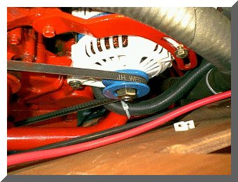
After testing the fit of the new alternator,
it became apparent that the raw water hose
is too close to the belt immediately
below the alternator pulley.
|
Upgrade (Page 4) |
Wednesday March 6, 2002
1. The new Balmar high output alternator arrived yesterday afternoon so today was dedicated to checking physical fit and planning the actual installation.
2. I first stopped to pick up a new Grade 8 mounting bolt and nylock nut as well as a new Grade 8 nut and bolt for the adjustment arm.
3. After test fitting, measurements were taken for spacers on mounting bolt. The alternator has 3.15 inch spacing between the feet and the Westerbeke mount was only 2.10 wide. I found that the included 1 inch spacer and six brass shims took up all the slack.
4. The raw water cooling hose from the raw water strainer to the raw water pump will have to be re-routed to give more clearance. You can see that it needs to be moved in the photograph below.
After testing the fit of the new alternator,
it became apparent that the raw water hose
is too close to the belt immediately
below the alternator pulley.
5. I called it a day fairly early so that I could go pick up the new engraved switch labels and the engraved labels for the Negative and Positive Distribution posts.

New engraved labels for switches
and distribution posts
Thursday March 7, 2002
1. Upon arriving at the boat this afternoon, I installed the new labels for the Battery Switch Panel.

Battery switches with new labels installed
2. Next I installed the labels for the Positive and Negative Distribution posts.

Positive Distribution Post with new label
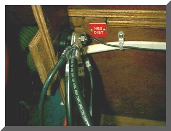
Negative Distribution Post with new label
3. The alternator was now bolted down with all the appropriate spacers, shims etc. and the adjusted for proper belt tension.
4. The rest of the afternoon was spent routing the cables and wiring between the Balmar alternator, In-Charge 3 stage regulator, Echo Charger, Link 10 and the battery banks.
5. With a little luck I hope to finish up the wiring tomorrow and possibly have time left over to methodically go through all the various testing procedures to insure that everything is working as advertised.
Friday March 8, 2002
1. This was the last day of running wires, crimping lugs etc. I finished all the new DC wiring today. Installing the batteries in the battery compartment was a tight fit, but not impossible. Since all of the battery boxes I have looked at have excess room in them once the battery is set in place, they take up too much room in the battery compartment so I intend to fabricate my own fiberglass battery boxes to fit the batteries.

Crowded battery compartment
2. With everything installed, I spent a fair amount of time cleaning up the mess I created during the installation and putting away a ton of tools. Tommorow I intend to test the entire system with the exception of starting the engine to test the alternator. I will hold on de-winterizing the engine for that test until I feel that we are out of the woods as far as any possible freezing weather is concerned.
Saturday March 9, 2002
1. After double checking all my wiring against my schematic drawings I energized the House Bank switch and checked that portion of the circuitry out using a digital volt-meter.
2. The In-Charge regulator was given what I would call a static check in accordance with the manual. No problems were encountered.
3. Next I secured the House Bank switch and energized the Starter Bank switch. The starter switch was momentartily energized to make sure I had power to the starter solonoid and starter motor. All was fine there.
4. The Emergency Parallel switch was then checked for proper operation.
5. With AC power applied to the on board 3 stage Charles battery charger, the Echo Charger was checked to insure that the Starter Bank was indeed receiving a charge from the House Bank.
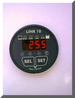
6. The Link 10 Battery Monitor system was the last item to be tested. At this point I only tested the basic functions and will test all of the advanced functions at a later time. First I checked that the Green LED bar graph was measuring how "full" the House Bank was.
7. The unit was then switched to the "Volts" mode to make sure it was reading the House Bank voltage accurately. The Link 10 reading was identical to that on my digital voltmeter.

Link 10 in "Volts" mode
8. I switched the unit to the "Amps" mode and turned on 4 interior lights of known current drain. If the House Bank is being "drained" the reading will have a negative (-) sign in front of it, and if the House Bank is being charged the reading will have no sign. The Link 10 read the current correctly.
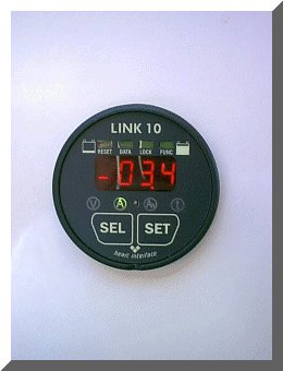
Link 10 in "Amps" mode
9. Next I switched to the "Amp Hours Consumed" mode. This represents the amount of energy "removed" from the battery. If 12 volt cabin lights that draw 4.0 amps total were left on for 2.5 hours, the meter would indicate 10 AH consumed (4 amps times 2.5 hours = 10 AH).
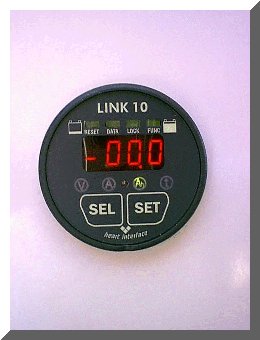
Link 10 in "Amp Hour" mode
10. The final basic mode is the "Time" mode. In this mode, the Link 10 gives a time estimate of how long the House Bank will sustain the load (the load is based on an average current drain during the last 4 minutes). This will tell you WHEN you need to recharge the House Bank.
Link 10 in "Time" mode
11. At this point in time, pending running the engine to check out the alternator, I have declared the system healthy and operational.
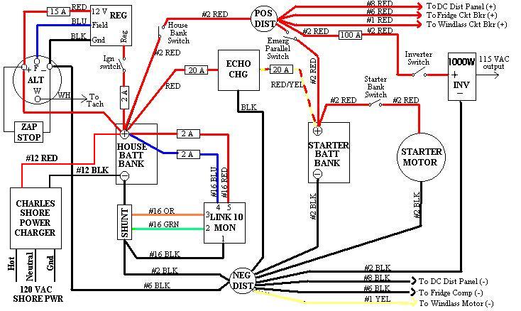
Wiring Diagram
Copyright 2001-2009 No duplication of any portion of this website without express permission.
Permission may be obtained by e-mailing the webmaster at
earlylight160@yahoo.com.