Now that the windlass was in place it was time to move on to the electrical phase of the installation.
Using my saber saw, I cut out a .75 inch by 3.25 inch hole to accept the 100 amp circuit breaker on the forward face of the quarter berth about where your left leg would be while sitting at the navigation station.
Circuit breaker installed
Note:
Running the positive and negative wires required drilling some
holes in some of the bulkheads with a 1 inch hole saw.
The positive (red) wire was run from the Positive DC distribution post in the engine compartment, through the compartment under the quarter berth where the hot water heater is located and to the 100 amp circuit breaker. From the circuit breaker, it was run forward on the port side outboard of the navigation station.
Rear of circuit breaker showing wiring
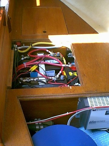
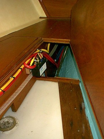
The negative (yellow) wire was run from the Negative distribution post in the battery compartment through the bulkhead separating the battery compartment from the hot water heater compartment. From this point on, both the negative and positive wires were run together to the v berth.
Negative wire connected to the negative distribution post will ultimately be run all the way to the windlass motor
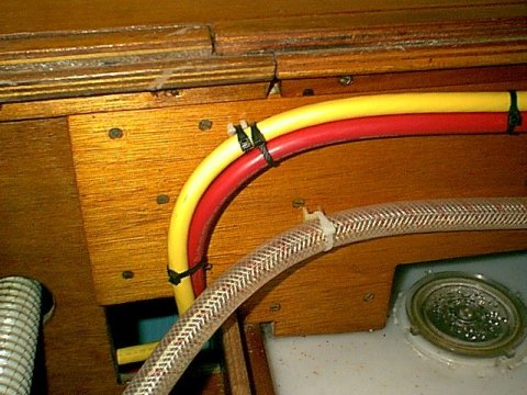
The wires were run under the port settee along the inboard bulkhead, then through the hanging locker and wardrobe drawers and into the v berth. All wiring was supported every 12 inches with cable ties attached to nylon mounts which were screwed to the inside woodwork along the wire path.
Routing through the forward portion of the port settee
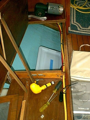
The wires were run across the port side of the v berth and through the existing opening to the starboard side of the fore and aft bulkhead above the holding tank.
Routing through the fore and aft bulkhead above the holding tank.
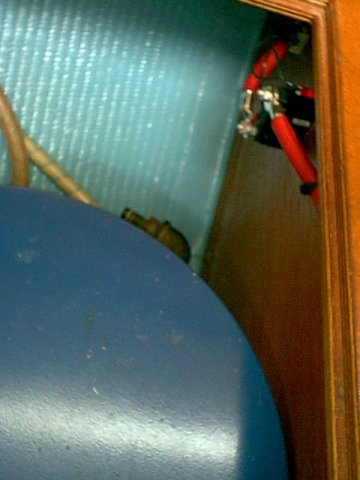
The SPA10700 Control Box was mounted on the starboard side of the fore and aft bulkhead at the forward end of the access panel and the positive wire was connected to the center large terminal. The negative wire will continue on forward up into the anchor locker behind the removable panel in the aft starboard corner of the anchor locker. It will eventually be connected to the negative terminal on the windlass motor.
Positive wire connected to Control Box and the negative cable awaiting final routing into anchor well
The Control box wiring was completed and the wires routed up to the chain locker behind the diagonal panel in the starboard aft corner. A hole was cut in the diagonal panel and the wires exit through that hole for connection to the foot switches and windlass motor. This hole was then sealed with caulking.
Control box with all wiring completed
Next, the two positive cables were run from the remaining two large terminals (UP and DOWN)on the SPA 10700 Control Box to the positive UP and DOWN terminals on the windlass motor.
The wiring from the foot switches to the SPA 10700 Control Box was now connected.
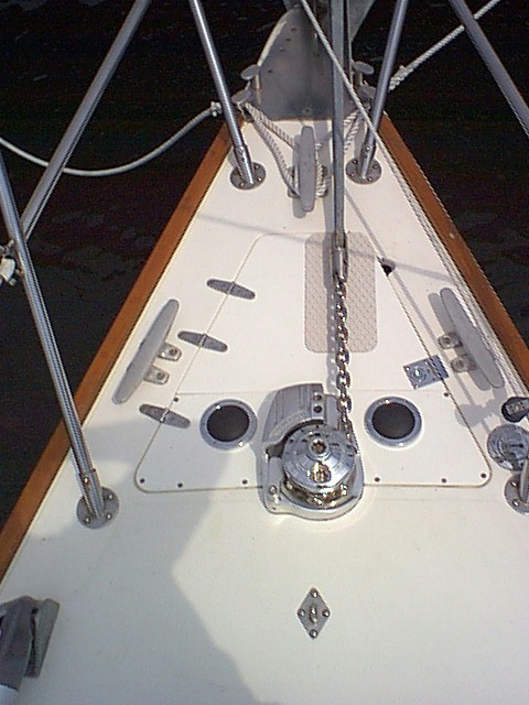
As a final touch I added a piece of Treadmaster to protect the lid from the chain and shank of the anchor.
Completed project
This completes the main wiring which allows operation of the windlass via the foredeck mounted foot switches. I made up the new anchor rode by splicing 150 feet of 9/16 inch premium nylon 3 strand twist from New England Ropes to the 70 ft of stainless steel 5/16 inch BBB chain. This was then installed and the bitter end secured in the anchor locker. All that remains to be completed is the wiring for the hand held remote back at the helm. This will be a separate project since it is now time to go sailing :-)
Copyright 2001-2009 No duplication of any portion of this website without express permission.
Permission may be obtained by e-mailing the webmaster at
earlylight160@yahoo.com.