


This page is still being constructed. More information will be added periodically. The quality of the photos on this page is far from brilliant but they should hopefully indicate most details. Consequently, I've tried to beat quality with quantity of photos! This explains the relative large number of photos available on this page which should include any part of the telescope for details. In any case, if you need some more details, let me know in the guest book.
Loads of credit has to be given to Joe Pearson (http://www.oocities.org/joe_pearson/). All the while during construction, most of my looking around on the net kept converging to Joe's excellent site! Most of the construction has been followed from Joe's experience.
Things which will be added to this page in the future are to include:
- construction drawings of the split ring telescope
- dimension calculations of the split ring telescope
- controller circuit diagram
- setting circle print file
Overall construction
The main construction material was water resistant MDF sheets and aluminium. MDF is a sort of material used in furniture making and is readily available from timber merchants. It is relatively expensive (in particular the water resistant type) and comes in sheets of 9 feet x 5 feet. A sheet costs around Lm24 (US$60) and two sheets were used for the construction.
The aluminium used was purchased from an aluminium wholesaler and consisted mainly of 20mm hollow tubes and 35mm x 2.5mm flat bars.
Any steel used was stainless steel, and these included threads, nut and bolts. Stainless steel is strongly recommended to avoid rust due to dew and storage.
The Base


The base is a triangular structure which holds the split ring. It is constructed in a way to hold the split ring at an angle of 36 degrees, this being the latitude of Malta. Threads mounted on the front apexes of the base are used to fine tune the inclination on site. The split ring is supported be a bearing at the back of the base (which accepts a bolt from the ring) and two bearings on the front of the base. Ring movement on the base is extremely smooth.
The Ring


The ring was made 3 sheets of MDF to get a thickness of around 35mm. The sturdiness of the split ring is essential for the performance of the telescope. I decided to go for a fixed split ring (as opposed to the 'folding' type found in Pearson's site) for better rigidity and retention of exact right angles. Having said this, this is traded with more space required for portability.
The outside of the ring is lined with a 35mm wide aluminium strip for a smooth surface and smooth movement on the bearings.
The ring was cut by using a jigsaw cutter with a long radius. I was impressed with the accuracy such a radius (made from an aluminium strip) can achieve.
Ring Mounted on Base

Mounting the ring on the base is simply a matter of first placing the back bolt of the ring in the rear base bearing and resting the aluminium strip of the ring on the two bearings on the front of the base. The aluminium strip on the ring was attached by using two hemispherical head screws at the end of the strip (top part of the ring). These screws act also as stops when the ring is rotated such that the open ends reach the bearings.
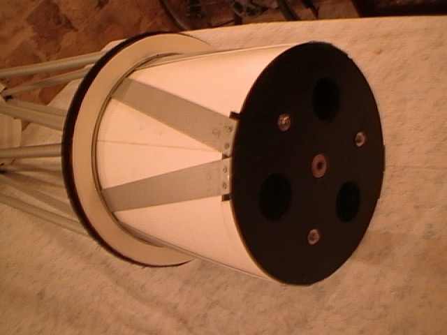
Lower cage (fixed) of Optical Tube Assembly
The lower cage was constructed from four octagonal 'rings' separated by stainless steel threads to achieve the required length of the cage. The top ring also has an aluminium ring inside on which the optical tube can rotate. The bottom plate of the cage also has a bolt which supports the tube (and mates with a bearing on the mirror cell) and keeps the tube accurately centred when rotated. Note the bottom plate is secured by 4 of the threads. The centre bolt of the bottom plate can be accurately aligned by slight movement of the bottom plate before securing these 4 nuts. The sides of the cage incorporates the bearing rings, lined with teflon and equipped with declination setting circles. The nuts on the top ring are recessed within the top ring as the tube assembly 'lip' needs to slide on this ring when rotated. The cage, when constructed in this manner proves to be relatively light and extremely rigid and solid. This is important to keep the tube collimated when rotated.


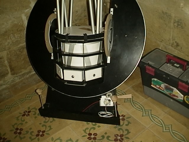
Lower part (rotating) of Optical Tube Assembly
The lower part of the ota is basically made from three elements:
- the bottom mirror cell
- the upper ring
- aluminium 'truss' flat bars.
The bottom is simply the mirror cell. Note the bearing in the centre of the mirror cell. This mates with the bolt in the fixed cage described previously. The top ring is also line with an aluminium strip which slides on the other aluminium ring on the fixed cage describes above.

The cell and the upper ring are secured using a system of eight aluminium flat bars slightly curved as in the photos. This results in a sort of truss bar construction which also provides a very rigid assembly. The inside of the lower rotating cage is then lined with a thin sheet of PVC (1mm thickness). The inside of the PVC is then lined with an adhesive sheet of black 'suede' type material.
Note also the recessed bolts in the upper ring holding the aluminium hollow tube truss rods.
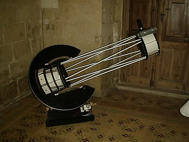
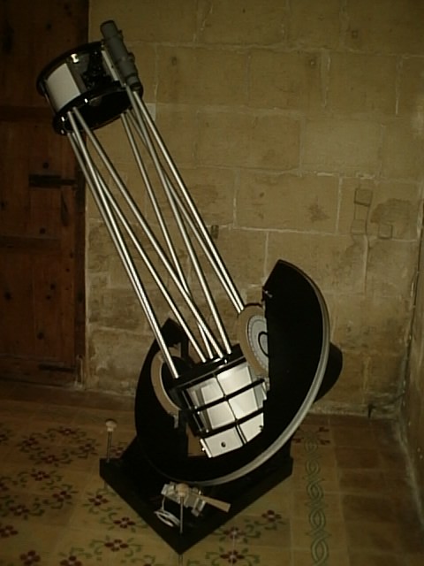
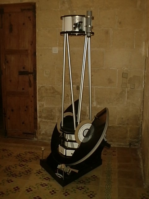
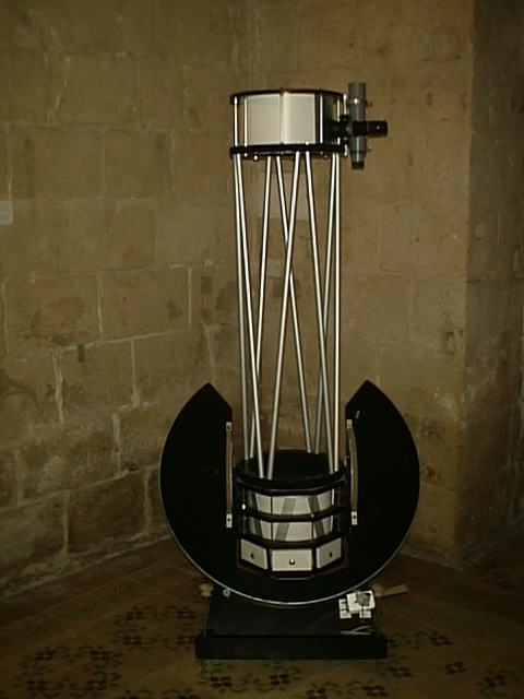
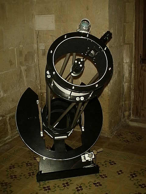
Optical Tube Assembly mounted on Split Ring
The ota is simply put inside the split ring. It is supported on the semi annular rings on the split ring. The teflon on the ota declination rings smoothens movement; however I have opted not to put in teflon strips on the ring. Two half rings fitted on the declination rings secure the ota to the ring and primarily provide to increase or decrease tension to control how stiff declination movement is required.


In order not to increase the ring diameter, I have opted to put the counterweight around the bottom fixed cage rather than at the bottom of it. The counterweights consists of two sets of three weights fitted onto an aluminium strip. Each of these strips will then be 'clipped' onto the threads of the bottom fixed cage, without requiring any fixtures. This method also proves convenient in ease of handling as the total counterweight weight came to around 12kg! Each of the six 'pellets' was made by melting 2 kg of lead shot in a rectangular mold and covered with PVC for aestethic purposes. These pellets were bolted to the aluminium strip.
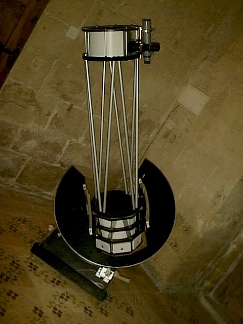
Optical Tube Assembly - Upper cage


The upper cage consists of two rings connected by aluminium threads. The use of aluminium will help make the top part of the ota as light as possible - a very important consideration when making split ring type of telescopes. The aluminium threads where made by threading 5mm aluminium rods. The inside of the upper part was then lined with 1mm PVC sheet, the inside lined with self adhesive 'velvet' sheet.
The truss rods
The truss rods are made of 20mm aluminium hollow tubes. The rings on which the truss rods where connected were accurately drilled with a 20mm bit and at an angle of around 5 degrees. This is the angle at which the trusses meet the bottom and upper rings. The truss rods would therefore seat within the rings - important for rigidity. Special effort needs to be made to make sure that geometric accuracy is maintained when handling the truss rod bit.
The truss rods where secured by means of a bolt, a nut and rubber washers in between. The rubber washers (around 2cm length), would be inside the truss tube. Tightening the bolt would squeeze the washers provide a sturdy fit within the truss tube. Tightening all the eight truss tubes in this way makes an extremely rigid, yet light optical tube assembly.
RA, Dec Motors and Controller
The split ring type of mount lends itself well for motorising. The RA motor mechanism is pretty straightforward to integrate, whereas the declination motorisation requires more thought in my opinion. All the mechanics and electronics are complete, however some finetuning still needs to be done to obtain an optimal drive system.
The motorisation system can be divided into two parts:
- the mechanical system, comprising of motor and gearboxes
- the electronic system, comprising of drive logic and controls.
The philosophy behind the complete drive system was to implement this with the least expense possible; to the extent that ALL parts had to be taken from the 'surplus' electronics and mechanics available in my workshop. The possibility to purchase a ready drive system was contemplated, however, due to the customised split ring design, substantial modification to commercial drive systems was still required. In the end, it was decided to build the drive system from scratch.
The features of the drive system can be summarised as follows:
- simple electronic circuitry
- hand control with x1, x2, x4, x8 for both RA and declination
- illuminated manual controls for RA+, RA-, Dec+, Dec-
- single battery source
- isolated (relay) interface for MX7 ccd autoguider control.
Motor selection:
Some experimentation with PC disk drive motors yielded that these were totally unsuitable for the split ring in question, mainly due to the torque available on these small motors. Two stepper motors (7.5 degrees per step, 24V dc) extracted from a defunct fax machine were perfect from the job.
Gearbox calculation:
A high reduction ratio was required to obtain the necessary torque as well as obtain a smooth operation as the split ring was required to cater for astrophotography. Against these two factors there is the maximum allowable rotation for the stepper motor.
Control logic
A simple circuit was required to provide the controls and stepper motor drive. A single supply in the form of a 12V battery was required to minimise complexity.


Mirror Protection caps

Dust and dirt are possibly one of the disadvantages of an open truss type design. I have washed the mirrors twice in a year; too much I know, but little or no harm has been noticed visually. Sheets made from 1mm PVC sheets cover the upper ota section and the lower primary mirror part. The bottom cover attaches through velcro strips to the cage while the upper ota two sheets are fixed by rubber bands held in place between the nuts on the upper and lower part of the upper ota section.
Eyepieces


The current collection of my eyepieces. The start was the 6mm plossl, 26mm super plossl and x2 barlow, all from Orion Optics - UK. The most used are the 26mm and the x2 barlow. The 26mm super plossl has a great view and little aberration is visible when this is used with the x2 barlow. The 6mm is rarely used mainly due to the limited eye-relief, and relatively poor optical characteristics.
The latest addition of the 9mm Type 6 Nagler is truly worth it's value. It's an outstanding eyepiece and with its wide field of view it is truly something to invest in. I was a bit disappointed with the Nagler x3 barlow. I believe that a Nagler eyepiece like the 9mm must be used on its own.
Other Photos