Section 1. Introduction, Overview and The Environment
STAAD-III for Windows / Windows NT is a comprehensive structural engineering
software that addresses all aspects of structural engineering - model development,
analysis, design, verification and visualization. STAAD-III for Windows
/ Windows NT is based on the principles of "concurrent engineering".
You can build your model, verify it graphically, perform analysis and design,
review the results, sort and search the data to create a report - all within
the same graphics based environment. With a live relational database at
its core, the Window based Graphical User Interface controls and manages
all the functions. Throughout this manual, it is assumed that the user
is well conversant with the Microsoft Windows Environment. If the user
is not familiar with Microsoft Windows, it is strongly suggested that before
using STAAD-III for Windows, the user go through the Microsoft Windows
documentation to get acquainted with its various features. Following are
the main options available from the Concurrent Graphics Environment -
STAAD- III Analysis and Design
STAAD-PRE Graphical Input Generation
STAAD-POST Graphical Post-Processing
STAAD-INTDES Interactive Design of Structural Components
The salient features of each of these facilities are described in Section
1 2 STAAD-INTDES Interactive Design of Structural Components The salient
features of each of these facilities are described in Section 1.2. The
Concurrent Graphics Environment also offers utilities for Plotting, Printing,
Editing, Viewing, On-line Manual access and File Management. Section 1.3
describes the Graphical User Interface Environment of STAAD-III for Windows
/ Window NT.
1.2 Overview of Facilities
This section contains a brief overview of the various facilities available
in the STAAD-III system.
1.2.1 STAAD - III Analysis and Design
STAAD-III performs the analysis and design of the structure. The processes
of analysis and design are integrated and can be performed in the same
run. STAAD-III uses a command language based input format which can be
created through an editor, the powerful STAAD-PRE graphics input generator
or through CAD based input generators. Output generated by STAAD-III consists
of detailed numerical results for analysis/design and sharp presentation
quality printer plots as part of the run document. Section 2 of this manual
provides a GENERAL DESCRIPTION of STAAD-III features, theories, assumptions
and conventions. Sections 3, 4 and 5 describe the STEEL, CONCRETE and TIMBER
design features. Section 6 provides detailed description of the command
language and specifications. The Example Manual contains a set of practical
Example and Verification problems.
1.2.2 STAAD - PRE - Graphical Input Generation
The STAAD-PRE facility allows generation of structural models graphically.
Powerful geometry generation algorithms facilitates generation and viewing
of structural models for both 2D and 3D situations. All other specifications
like section properties, material constants, supports, loads, analysis/design
requirements, printing/plotting requirements etc. are available. As the
output, this option generates the STAAD-III command language based input
file. Section 7 of this manual provides a detailed description of all facilities
available in STAAD-PRE. A comprehensive tutorial is also available in the
same section.
1.2.3 STAAD - POST - Graphical Post - Processing
STAAD-POST is a powerful graphics facility for verification of the
model and display of the results. The model verification capabilities include
complete graphics verification and visualization for all items. State-of-the-art
results verification capabilities include display and plotting of structure
geometry, deflected/mode shapes, bending moment/shear force diagrams, stress
contours etc. A versatile "query" facility allows generation
of customized reports. Powerful icon-based graphics tools provide extremely
user-friendly navigation and manipulation capabilities. STAAD-III can be
invoked directly from the graphics environment allowing "concurrent"
verification and visualization. Sharp presentation quality plots may be
generated on all plotters and printers. Section 7 contains a detailed description
of all available features and facilities of STAAD-POST. A comprehensive
tutorial illustrating the usage of the facilities in STAAD-POST is available
at the end of that section.
1.2.4 STAAD - INTDES
This option contains a set of interactive design facilities for structural
components. The currently available options include design of Cantilever
Retaining Walls, Footings and Slabs.
1.2.5 Utilities
Apart from various Windows facilities like temporary exit to other
programs running concurrently with STAAD-III for Windows / Windows NT,
STAAD-III for Windows / Windows NT also offers the following utilities
within its Graphical User Interface Environment -
· Text Editor - for creating/editing the input file
· View facility - for viewing the output file
· On-line Manual - for detailed information about STAAD-III
commands as explained in the Reference Manual.
· Print/Plot facility - for printing and plotting the output
file and graphics screens
· Data Exchange with CAD programs - for import/export of drawing
data
· On-screen calculator - for interactive arithmetical calculations
The Text Editor is available from the Main Menu as well as from the STAAD-PRE
facility. It is also accessible as an independent application from the
REI applications group. This can be used for creating new input file, viewing/editing
an existing input file and viewing/editing an input file created by the
STAAD-PRE Graphics Input Generator.
Section 1 5 The View facility is available from the Main Menu as well
as from the STAAD-POST facility. This facility can be utilized to view
the entire output file on the screen. Both numerical data and graphics
output can be viewed. The Print facility can be utilized to print the output
file. It can be invoked both from the Main Menu and from STAAD-POST. The
Plot option allows plotting of graphics. Plots generated in STAAD-POST
print/plot option may be plotted directly or by using the Plot option of
the Main menu. Data Exchange facility with CAD programs is available. The
STAAD-PRE facility can read ".DXF" files to generate STAAD-III
input. Both 2D and 3D ".DXF" files may be generated for graphics
plots created in STAAD-POST using the Plot option. An interface to the
Microsoft Windows Calculator is provided for quick interactive arithmetic
calculations required during input generation or result verification. The
Calculator is available in STAAD-PRE, STAAD-POST and the STAAD-INTDES.
STAAD-III for Windows / Windows NT may be interrupted by pressing Alt-Tab
key any time (except while the program is performing the solution process
of a problem). The user may use this facility to switch to any other WINDOWS
program running concurrently. The user may also exit to DOS temporarily
from the Windows environment using the MS-DOS icon in the �Main� Program
Group under the Windows Program Manager. The original environment of STAAD-III
for Windows / Windows NT can be resumed by switching to the STAAD-III Window
using the Alt-Tab key again. Section 8 of this manual describes the Editor,
View, Print and Plot options in detail.
1.2.6 STAPLE
STAPLE stands for STAAD-III Application Programming Language Extension
. It is a unique and innovative script language that allows you to build
a customized structural engineering solution using STAAD-III. STAPLE utilizes
a simple English-like command language format that is extremely easy to
learn and use. Using STAPLE, you can access the STAAD-III database to extract
all structural data -geometry, section/material properties, forces, moments,
and more. Use it to integrate and execute your in-house, company-standard
programs seamlessly with STAAD-III. Create new programs that enhance your
productivity. Combine your own knowledge and expertise with STAAD-III�s
powerful analysis and design features. In other words, get a customized
STAAD-III tailor-made to your specific structural solution needs. Section
10 of this manual introduces you to the fundamentals of STAPLE. It starts
with a quick overview of STAPLE using a simple example. Following that,
all the STAPLE commands are described and illustrative examples are provided.
Graphics related STAPLE commands are also discussed.
1.3 The Graphical User Interface Environment of STAAD-III for Windows
/ Windows NT
The STAAD-III for WINDOWS / WINDOW-NT software system is built around
a state-of-the-art graphics environment based on the principles of "concurrent
engineering". This user-friendly environment allows easy navigation
within the various facilities of the software. A live relational database
integrates the various functions into a single unified software system
allowing "concurrent" data generation, analysis/design, visualization
and verification. In addition to the main engineering facilities, the Section
1 7 Graphical User Environment offers various Editing, Viewing, Printing,
Plotting and system related utilities. After successful installation of
STAAD-III for Windows / Windows NT, the STAAD-III Program Group will be
created under the Program Manager for Windows. Please refer to the Program
Installation Documentation in the Getting Started Manual for a complete
discussion on the program installation procedure. The STAAD-III for Windows
/ Windows NT environment is invoked by clicking the STAAD-III icon in the
STAAD-III Program Group under the Program Manager for Windows. The initial
screen is as shown below. The current Revision No. and the type of the
STAAD-III version (PC Unlimited, PC 500 etc.) are displayed on the screen
as the Window Heading. STAAD-III for Windows / Windows NT uses a hardware
lock to validate its capability. If the hardware lock is not found, the
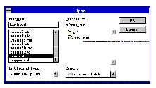
program will run in the "demonstration mode." When the STAAD-III
application is activated, the user is prompted to specify the file name
for opening either new files or existing STAAD files. Before any operation,
the user must specify an input filename. The File option of the main menu
may also be used to open files. The Open submenu under the File menu should
be used to specify the name of an existing file (one that already contains
the input data). The New submenu under the File menu should be chosen to
specify the name of an input file for a structure whose input data is to
be created. It is to be noted that all STAAD input files must have an extension
".std". Once the file name is specified, the user is allowed
to invoke other options available in the main menu area. One exception
to this rule is that the STAAD-PRE option may be invoked without specifying
any file name from the main environment of STAAD-III. However in that case,
the user must specify the appropriate file name using the File option of
the STAAD-PRE main menu. The following list shows the suggested project
development sequence for solving your problem with STAAD-III. The order
is quite flexible.
- 1. Create the STAAD-III input file with the Edit Input option, or with
the STAAD-PRE graphical modeling option. You may also import files from
your CAD software using the STAAD-PRE option.
- 2. Enter the STAAD-PRE option with partially complete input files or
the STAAD-POST option with complete input files to check the model graphically.
- 3. Perform the analysis and design with the STAAD-III option on the
main menu screen or with the Run STAAD icon in the toolbox in the STAAD-POST
environment.
- 4. Verify the analysis results and designs reported in the text output
file. This can be done with the VIEW OUTPUT option on the main screen or
with the RESULT and QUERY items in the STAAD-POST option.
- 5 Verify the analysis and design results graphically with the Result,
Report, Query and Icon items in the STAAD-POST option.
- 6 Generate necessary plots using the STAAD-POST facility.
 Getting Started
Read This First
STAAD-III is a comprehensive structural software that addresses all
aspects of structural engineering - model development, analysis, design,
visualization and verification. This version of STAAD-III is based on the
principles of "concurrent engineering". You can build your model,
verify it graphically, perform analysis and design, review the results,
sort/search the data to create a report, and more - all within the same
graphics based environment. With a live relational database at its core,
the Concurrent Graphics Users Interface (CGUI) controls and manages all
functions. This Getting Started section introduces you to the fundamentals
of using STAAD-III. It provides information on Hardware requirements, Installation
and Operation of STAAD-III. An Introductory Tutorial will guide you through
the processes of -· Creating an input file - graphically or through
a text editor · Running STAAD-III to perform analysis and design
· Visualization and verification of the model · Review/Verification
of results - graphically and numerically · Printing and plotting
In addition, this manual has been designed to serve as a quick reference
to STAAD-III commands and menus. Refer to the Appendices for a summary
of STAAD-III commands and Research Engineers' technical support procedures.
Hardware Requirements
The following requirements are suggested minimums. Systems with increased
capacity provide enhanced performance. · 486 PC w/ math co-processor
· SVGA Graphics · 12 MB Free RAM (see note) · DOS
6.0 · Windows 3.1/Windows 95/Windows NT · Sufficient free
space on the hard disk to enable 30 MB virtual memory + 20 MB free space
for running STAAD-III Note: Additional RAM significantly enhances performance
of STAAD-III and of Windows. You can increase the memory available by creating
more Virtual Memory in your Windows configuration. Virtual memory, however,
runs applications slower than real memory. See your Windows documentation
and section 4 in the following pages for more information on system configuration.
Getting Started
Read This First
STAAD-III is a comprehensive structural software that addresses all
aspects of structural engineering - model development, analysis, design,
visualization and verification. This version of STAAD-III is based on the
principles of "concurrent engineering". You can build your model,
verify it graphically, perform analysis and design, review the results,
sort/search the data to create a report, and more - all within the same
graphics based environment. With a live relational database at its core,
the Concurrent Graphics Users Interface (CGUI) controls and manages all
functions. This Getting Started section introduces you to the fundamentals
of using STAAD-III. It provides information on Hardware requirements, Installation
and Operation of STAAD-III. An Introductory Tutorial will guide you through
the processes of -· Creating an input file - graphically or through
a text editor · Running STAAD-III to perform analysis and design
· Visualization and verification of the model · Review/Verification
of results - graphically and numerically · Printing and plotting
In addition, this manual has been designed to serve as a quick reference
to STAAD-III commands and menus. Refer to the Appendices for a summary
of STAAD-III commands and Research Engineers' technical support procedures.
Hardware Requirements
The following requirements are suggested minimums. Systems with increased
capacity provide enhanced performance. · 486 PC w/ math co-processor
· SVGA Graphics · 12 MB Free RAM (see note) · DOS
6.0 · Windows 3.1/Windows 95/Windows NT · Sufficient free
space on the hard disk to enable 30 MB virtual memory + 20 MB free space
for running STAAD-III Note: Additional RAM significantly enhances performance
of STAAD-III and of Windows. You can increase the memory available by creating
more Virtual Memory in your Windows configuration. Virtual memory, however,
runs applications slower than real memory. See your Windows documentation
and section 4 in the following pages for more information on system configuration.